The top dashboard has some front-to-back cracks. I previously filled in the cracks with vinyl repair epoxy, but intended to cover the whole thing with a new piece of vinyl. I started off well, using contact cement, but hit a snag with the drastic compound curve just to the right of the instrument cluster hump. It just wasn't possible to get the vinyl to stay flat. I gave up and found a dashboard restoration outfit with a vacuum press on the web and emailed them but never got a response.


So I think I'm going to use the rest of the vinyl repair kit to try to do the best I can to clean up the cracks. Since I was disillusioned by the dashboard, I decided to install the passenger compartment hardware.
I decided to start by attacking the emergency brake handle. It was a chipped paint and rusty mess. I soaked it in the magic fluid, then sanded, primed, painted and clear coated.


After assembly, I'm left with a pressure switch that looks like it should screw down into the side-to-side brace just under the handle, but it doesn't fit anyway I try. I tried searching Google for images but nothing is helping. I'll leave it off for now but will keep it in a labelled ziplock bag just in case.

Next I moved to the pedal cluster. I had previously fixed it up, so it's just a matter of bolting it into place. Right... Cramped spaces, tiny hardware, cables, etc. make it quite difficult. I pushed the brake actuator into the master cylinder and ran the nuts onto the studs to lock it into place. You'll notice a bad cable connector below that I'll fix up later.

Then I bolted the cluster down to the floorpan and hooked up the clutch and accelerator cable. Two problems: the clutch cable is new and despite adjusting both ends it looks like it's too long. This will be fun to figure out later on. The second problem is the pivot pin for the accelerator cable mount was worn about halfway through. I replaced it with a bolt and nylock nut so I don't get stranded on the road somewhere.


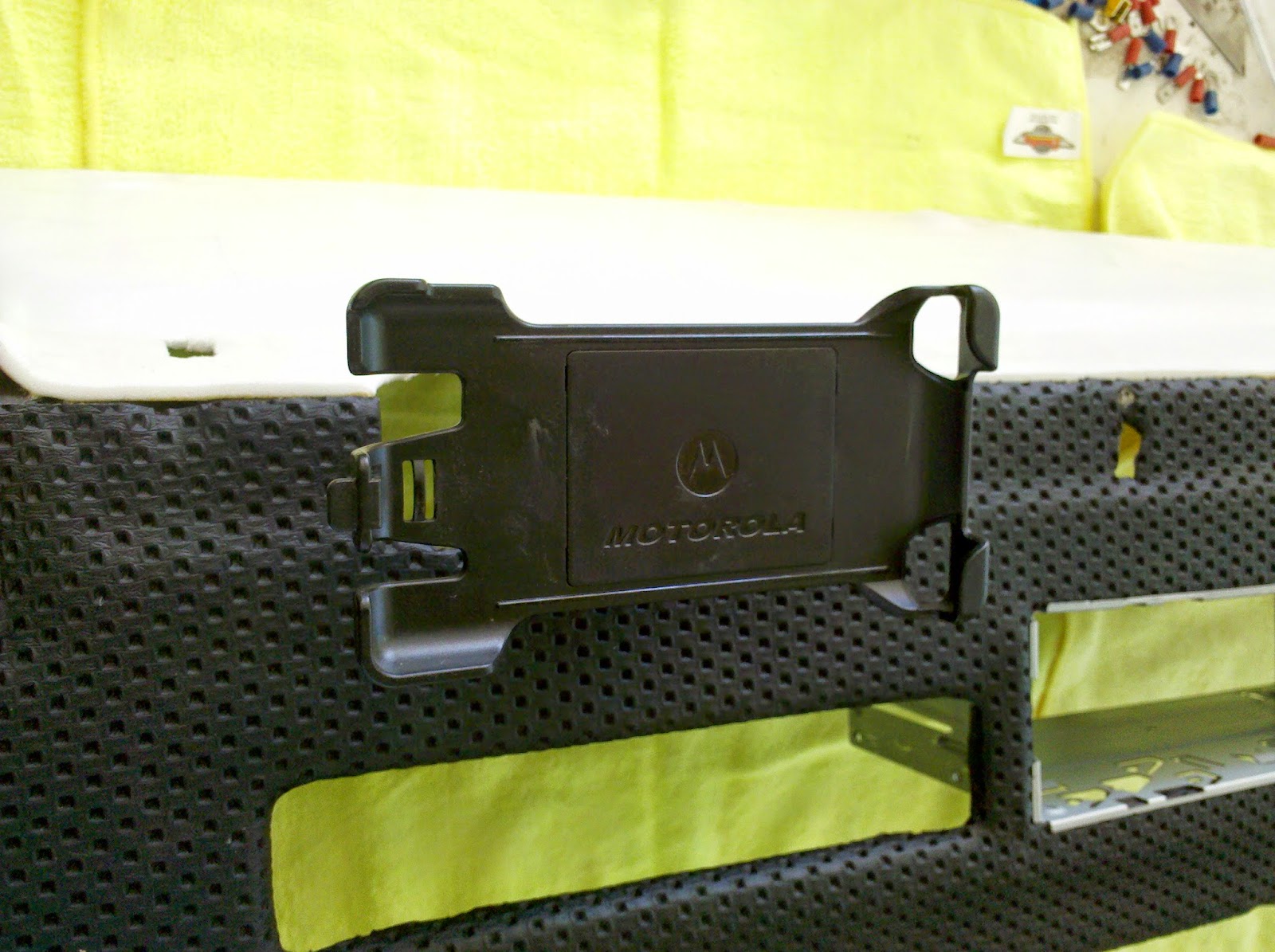
We now move a couple of weekends into the future and I went back to installing the "middle" dashboard. First thing I did was install the PakTrakr display and the radio housing into an enlarged hole where the cigarette lighter used to go. I will install a 12 V outlet later, not in the face of the dashboard but out the bottom so plugs will stick up into it vertically.


I gently laid the dashboard frame into place on the firewall, pushing the four bolts along the top edge down into their holes. I learned the hard way in this project that tightening things up during a multi-step process usually results in taking something apart again. I left the dash unbolted while I worked on mounting the rest of the hardware and running the cables.
One slight mistake I made was to leave the switches plugged into the wiring harness during the bodywork. I should have removed them or put them into plastic bags and ziptied up inside the firewall. This resulted in the soda blasting powder getting onto and into the three switches. I carefully marked the wire color codes, removed, cleaned and replugged the switches.
The headlight switch was the most challenging because as I was blowing compressed air into the switch to get the powder out, the interior light dimming rheostat wire coil popped out. This necessitated taking the switch fully apart so I took the opportunity to clean and lubricate everything well.


Working from left to right, I mounted the headlight, hazard light and fog light switches. Once mounted, I gently convinced the wiring harness into place behind the dashboard and plugged each wire into the proper place.
This is the hazard light switch, followed by the fog light switch, dirty and clean.


And here are the completed switches.

Next it was time to install the heater control. First I cleaned it well, lubricated the pivots and burnished the copper contacts for the first, second and third fan speed. The tricky thing is to get the three cables that come through the firewall from the ventilation system attached to the right lever arm. I got everything mounted but then found the bottom slider only went about 1/3 of the way across. I traced this back to the amount of exposed cable on that control. It just didn't have enough travel. I cut about 1" off the end of the armor on that cable and re-mounted it. That did the job. Why it didn't work correctly I don't know, but all three controls work well now.


I popped the driver's side door switch onto the cluster of brown wires. I cleaned the contacts in the switch well, then washed the slightly cracking rubber and treated it with rubber preserver. The passenger door switch is around the shop somewhere, but I can't put my hand on it right now. I hope it eventually shows up!

Next I moved to the instrument cluster. I sanded down, primed, painted and clearcoated the instrument cluster frame and screwed it into place.

I gently pulled the wires for each instrument through their respective holes, plugged onto the terminals and pushed in the light bulb holders into their sockets. I tested the odometer one more time before installing and found that it was failing again - no motion on either odometer. Following the Pelican Parts tutorial, I found mine had the "slipping gear" problem, so I gently squeezed the center hole with vice grips and now it grabs nicely on the shaft and behaves properly. Nothing like a friction fit on a polished shaft - future failure guaranteed.
I followed my wiring diagram from the disassembly and found a couple of things I need to tweak. Once all wires were in place, I screwed in the speedometer cable and trip odometer reset cable and pushed all of the instruments gently into place. It's starting looking like a car again!

I then started to put the steering column back together, but I decided that the ignition switch/lock wasn't working very well so I've taken it to an automotive locksmith to be cleaned & rebuilt and have a few new keys cut, so that installation will happen this coming weekend. I have also transferred over to the 924 indicator/wiper stalk assembly, using the Pelican Parts tutorial, and will have pictures of that next time. This gives me electric control of the new windshield washer pump.
So good progress and we're getting very, very close to checking the 12V electrical system! Oh yes, I ordered the 20 US Battery batteries last week and they should show up any day, so I need to move quickly through the rest of the project to get it into rolling state. I'm not going to worry about doors or hoods or windshields, just enough to roll it around and do the initial testing!


