Saturday, January 29, 2011

Front and Saddlebag Battery Racks

Having attacked the engine battery rack, I moved to the front.  Simple, right?  Just drop it in, drill a few holes and stick in some bolts.  Well, close but no EA cigar!

I positioned the rack in the compartment and found that no matter what I did, there is a 1" gap between the front mounting tabs and the bottom of the car.


A helpful person on the 914EV forum said he also had a gap that he filled with a long bolt and a stack of washers.  I will do the same with some washers and a short tube.

Now we move on to the excitement of the saddlebag battery racks.  Surprisingly, it went very smoothly.  I used the templates to mark the outline and drill the mounting holes.


I then cut the shape out with a jigsaw with a metal blade.  I taped the opening to avoid marring the surrounding paint.  It took several test fittings and trimmings to get the rack to fit, then I filed the opening smooth.


Due to the ribs, EA supplies shims to give a level surface for the rack to mount to.


Luckily for me, Lowes carries the special metallized silicone specified in the EA manual.  It said to use a lot of sealant around the hole and the bottom of the rack to make a complete seal.  Well I went way over the edge on the first mount and had a lot of nasty cleanup.  I used significantly less on the second rack and it went in nicely.  I used a lot of paper towels to clean up the excess, on the top and bottom of the hole, and mineral spirits to get it perfect.  I was surprised to find that the bottom of the rack is only about 3/8" above the CV joint bracket where it bolts to the transmission.  You can see the CV boots below.  Neither of these should move while driving so theoretically it should be fine, but I may end up putting in some spacers to lower the transmission a smidge.


I also added the hydrogen gas vent to the rear trunk compartment.  The battery boxes will have tubing and fans installed to get rid of the gas generated by the batteries as they do their battery thing.

Saturday, January 22, 2011

Day of Destruction - Engine Battery Rack Prep

Before I get to the destruction, I wanted to show the result of prepping and finishing the metal around the interior of the passenger compartment.  If you go back a bit in time, you'll see that the car was caught in the rain with bare metal exposed in the passenger compartment.  I would have thought Rainbow would have blasted, primed and painted the compartment, but it didn't happen.  I had to scrape off most of the existing rubberized coating to expose the rusty parts.  I then treated it with my magic rusty solution.  I then used about 6 cans of 3M rubberized undercoating spray.  Trust me, a can doesn't go very far.  It's basically thinned tar.  I masked off the area, then sprayed multiple coats and I think the final result looks great.  I've dealt with the rust, and added a temperature stabilization and noise reduction layer.


Now, on to the destruction.  During the tear down, I read the EA directions and it said remove the engine cover release bracket so the engine bay battery rack will fit.  So I unbolted the catch mechanism from the mount welded to the rear of the rear engine firewall.  The car was then painted and now I come to realize, with some advice from the helpful folks on the 914EV forum, that I was meant to remove the mount too, and the hard tube that shepherds the release cable from the passenger compartment!  This was going to be ugly, given the delicate nature of removing a welded metal bracket from a newly painted area.  You can see the tube curving in from the right and attaching to the mount.


The tube is very stiff and tack welded to the frame as it comes out of the passenger compartment, so I decided to cut it off, and I'll pop a small rubber cap on later.


Here's a closeup of the mount we need to remove.  I taped off the areas I was likely to bang into for a little protection.  I had to climb inside the engine compartment to get the proper access.


With the use of a sawzall, jigsaw with a metal blade and angle grinder, the mount is now gone.  I painted it with rust fluid and will prime and paint to match the body later.  It came off better than I thought it would.


I tried a test fitting of the battery rack and immediately found the original 12V battery tray needs to be removed too.  I just missed that in the instructions.


I did manage to remove it, with the help of the tools listed above.  I didn't take an after-picture, so I'll put that up later.  The good thing is when I got the tray out, I found a strip of rust under the horizontal tab of metal you can see welded to the vertical panel.  This would have been a rust farm in the future.  They weren't able to reach it with the blaster and the primer and paint couldn't get up underneath well enough.  I slathered it with rust solution and it's in good shape now.

Tuesday, January 18, 2011

The Motor and Transmission are In!

I was looking forward to a 3-day MLK holiday weekend and making great progress on the car, with the specific goal of having the motor and transmission mounted in the car, the driveshafts installed and the shift linkage in place.  I managed to get all of that plus a little bit.

Alert readers will remember last weekend we mounted the motor to the transmission and placed it under the car, but stopped there.  I backed the assembly out and worked on separating and repairing the bundle of cables coming into the engine compartment.


I cut the tape wrapping I applied during tear down and separated out the wiring harness that leads to the rear brake lights from the accelerator, clutch and speedometer cables.  I noticed that the clutch cable's outer plastic covering was worn, so I cut out the bad part and slipped a section of heat shrink tubing over the damaged area.


The speedometer cable has a similar worn area, but the connector on the end is far too big to slip a piece of shrink wrap over, so it will have to live that way.

I mounted the new rubber transmission mounts, then pushed the motor and transmission assembly into place and jacked it up to where it was touching the front and rear mounts.  I snugged up the transmission bolts and ran the bolts into the front engine bar mount, pushed the whole thing forward and tightened all four bolts.


I was thrilled to get to this point.  My joy was short-lived though when I realized that I hadn't inserted the front shifter shaft into the hole in the firewall.  I put the lift back in, removed the front mount bolts, lowered the lift down enough to replace the shaft bushing in the firewall and insert the shaft.  I then raised the lift and bolted the motor bar back in place.  Then I installed the rear shifter bar, keying it into the front bar and the assembly at the shifter pivot on the side of the transmission.  I bought a bushing kit from Pelican Parts and replaced the allen keys and plastic bushings.  As Edd on "Wheeler Dealers" would say "The bushes have perished".  These nice new parts will give me factory-crisp shifting.


Unfortunately the rubber boot covering the shifter pivot above was missing on the car and seems to be unavailable on the market.  I'll keep checking but if anybody knows where I can get one, please let me know.

Now I moved on the drive shafts and this is where things got, er, interesting.  The passenger side drive shaft splines went into the hub like hot butter.  I tightened up the hub nut and the CV to the transmission.


Then I went to do the other side.  First I realized that I couldn't maneuver the shaft into place with the shifter installed, so I removed the rear shifter rod.  Then I found the shaft wouldn't fit in the space between the hub and the transmission, by about 1/4".  I had to loosen the 4 bolts holding the motor and transmission assembly in place in order to get that space I needed.

Then I found that the splines on the shaft wouldn't go into the wheel hub no matter how hard I tried.  I took it back out and tried to fit it into the hub from the tire side, still no luck.  Upon closer examination, it looked like the start of the splines on the shaft were slightly damaged, likely by Rainbow tightening the nut down too tight when they removed it.  I got a fine triangle file and gently filed open every spline.


I cleaned the splines on the shaft and the hub and lubed it, then jammed it in, with some help from a rubber mallet, on the tire side and pulled it out over and over until it went in all the way.  I then tried to put it in from the correct side and could just barely get the splines engaged, but no further.  I then noticed a small dimple hole in the end of the shaft and that gave me an idea.  I drilled the hole about 1" deep, then tapped it for a 1/4" x 20 bolt.  I ran in a bolt and grabbed the bolt head with my biggest hammer and pivoted hard against the hub.  To my amazement, it slowly slid into place enough that I could get the nut on and pull it in the rest of the way.  I then bolted the other end to the transmission and tightened up all of the mounting bolts.


I re-attached the shifter shaft, and then went to work, cleaning and installing the clutch cable pulley assembly.


Strangely there doesn't seem to be a protective cover on the clutch pulley assembly.  To me, it should be protected from dirt and abrasion damage.  I then installed the speedometer cable and zip-tied it to the clutch cable.  Behold the awesomeness of the power plant of the car!

Wednesday, January 12, 2011

A Very Busy Weekend!

With the hub adapter in hand, it was time to mount the transmission to the electric motor.  I haven't seen an errata sheet for the EA kit, but I'd sure like to start one.  I've had issues with all 3 steps I've tried to do so far...  This weekend I'm very thankful I live about 3 miles from a Lowes store, as I made 5 trips there... 

Anyway, let's begin.

The first thing I did on Saturday morning was bolt the motor mount to the motor (duh).  You're supposed to position the motor with the wiring studs pointing down.  See how there are only 4 possible holes to bolt the mount to the motor?  Hard to get this wrong eh?  The bolt size of 3/8" in the manual and parts bag is too big, the machined holes are actually 5/8".  So off to Lowes I go.  I bolted it on, and it came back to bite me in the ass.


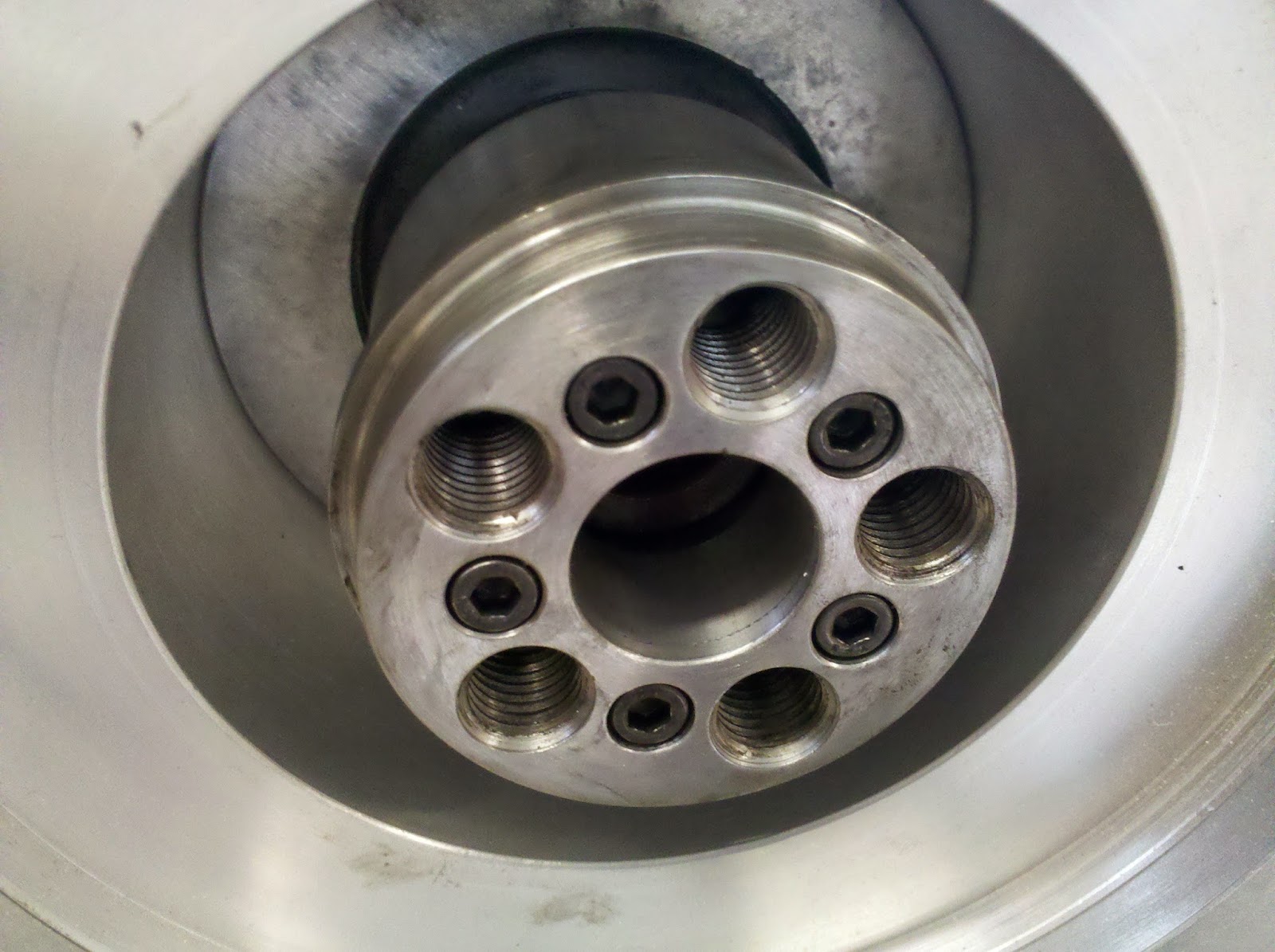
I then bolted the thick spacer and then the transmission adapter to the electric motor.  These get Loctite'd (not in the kit, off to Lowes I go) and torqued down.  I borrowed a small and large digital torque wrench from my buddy Gary.  These big bolts actually have hex key heads and of course there isn't one in the EA kit.  I don't have a hex key of the right size with a 3/8" or 1/2" socket that will snap onto a torque wrench.  So I saved myself a trip to Lowes and Macgyver'd one up.  I cut a part off of a proper sized hex key, and inserted it into a hex socket of the proper size that snapped onto the torque wrench.


Note that the instructions say only to put the "flat" part to the bottom and the left side.  I thought I did this right, as you can see in the picture above.  This will come back to bite me in the ass.

Next I placed the drive shaft key into the motor shaft, then place the two parts of the hub onto the shaft.  You gently tighten the screws pulling the two pieces of the hub together, allowing it to slide a bit on the shaft, to set the flywheel at the proper distance.


Next, I prepped the flywheel by replacing the throwout bearing and O-ring.  These are cheap from Pelican Parts and well worth the investment while you have everything torn apart.  The flywheel is gently bolted to the hub, and then you measure the distance from the outside edge of the flywheel to the transmission adapter plate, very very carefully to three decimal places.  You adjust the distance, and when it's right you carefully take the flywheel off and tighten the hub.  You put the flywheel back on and double check the distance, rinse and repeat.  When perfect, you Loctite the bolts and tighten everything down.


Next the clutch gets bolted in.  The existing clutch in the car was in excellent shape, with no cracks or evidence of oil soaking, so I saved a few hundred dollars by reusing it.  I did buy a clutch rebuild kit from Pelican Parts, and replaced the parts as I went.


Next I moved over to the transmission to prepare it for mating to the motor.  The focus is on the clutch throwout arm and bearing.  This is attached to the clutch pedal via a cable, and causes the clutch to engage and disengage against the flywheel.  The throwout assembly was very grimy and dirty, to the point that the bearing wasn't spinning against the spring tabs on the clutch.  I took it apart and cleaned it well and it started spinning freely.  I replaced the wear and tear parts on the arm, and made sure the arm itself was still flat and true.  The bearing wasn't sliding on the shaft well, so I cleaned everything off and sanded down some rough metal to 2000 grit, then used moly lube and it now slides like hot butter.


Now it was time to mate the transmission to the motor+adapter plate.  After some wiggling, I got it onto the splines and pulled the two together.  This is when I realized the transmission and the adapter plate didn't line up.  This is where the ass biting really came into its own.  It wasn't just a little bit off, it was a lot off.  I couldn't simply rotate the motor around until it matched up because the wire studs and the motor mount would be in the wrong place.  So I took everything off, including those Loctite'd freaking bolts.  I then figured out the correct orientation of the adapter plate to the transmission and  then bolted everything back onto the motor.  The adapter plate was nowhere near the orientation they suggest in the manual.  An accurate statement and a picture/diagram would have been a great help and saved me about 2 hours.  I should have double checked with a dry fit before bolting everything.  I've now learned my lesson and will do so from now on.

I bribed Fred again with pizza and beer, so he came over on Sunday morning.  We had the pizza but forgot about the beer which is probably a good idea.  We were going to be doing heavy lifting and there's no way I could do it myself.  The manual recommends an engine hoist but I figured two middle aged guys could handle it.

Flashing back to yesterday, the motor wire studs are in the right orientation and the adapter plate matches up with the transmission.  But the kicker is the motor mount on the other end is now wildly off.  Remember it can only be mounted in 4 orientations and unfortunately the orientation I need is not any of them; it's somewhere in between.  Now I'm thinking I was sent the wrong motor mount, or the motor manufacturer changed the spec and EA didn't know or didn't update the manual.  I wanted to move forward so I had to drill two new mounting holes.  Of course the position of the holes are blind behind the plate, so I had to insert sacrificial bolts (off to Lowes we go) into the two possible holes, then grind them to a point and lock them into place.  I carefully measured the gap from the mount to the motor, using a socket wrapped in tape to give the right dimension, and the center line of the mount.  I held it in the correct position and Fred tapped the plate with a rubber mallet on each point.  We then drilled out the hole locations and bolted the mount to the motor.  The ass biting was complete.


Now it's time to roll the motor+transmission out of the shop so we can mount the original 914 engine mount bar to the electric motor mount.  I used a nice hydraulic jack I borrowed from Gary, plus a furniture dolly and two pieces of plywood.  Not a recommended design, but it worked for me.


The manual's description and supplied bolts for the bar mount are too long - they run out of thread before tightening down.  The bolt goes into the engine mount bar, rubber spacers with metal sleeve (not listed in the manual), the motor mount and then a nylock nut.  Even by adding several washers it wasn't able to tighten down all of the way.  Off to Lowes we go for a bolt 1/2" shorter.  We bolt it on, then roll the assembly under the car and jack it up into place.


At this point we were losing the light and I decided I needed to clean and paint the transmission and motor mount hardware, so we called it a day.  We made a huge step on the project, but ran into a multitude of problems with the EA instructions and supplied parts.  I'm hoping the quality of the kit improves dramatically.