Monday, December 14, 2009

Drop The Engine!

With the 12-point star driver in hand, it was time to do the biggest project yet - dropping the engine and transmission out of the car.  The engine and transmission actually drop out of the bottom of the car, not pulled up from the top like most other cars.  Having read the other conversion blogs, I figured I could drop it down gently, but it didn't turn out quite that way...

Fred came over on Sunday, bearing pizza.  Feeling satisfied after a good lunch, we laid out our strategy.

First we removed the axles from the transmission at the CV joints.  Using the star driver, it was easy.  The driver's side axle can be locked with the emergency brake, but on the passenger side I had to wedge my knees against the wheel and hold it with my hands.  The important thing is to put a bag over the axle end because it's a greasy mess. You can zip-tie the passenger axle to the spring to keep it out of the way, but the driver's side is impeded by the starter motor.  You just have to work around it as you roll the engine out.

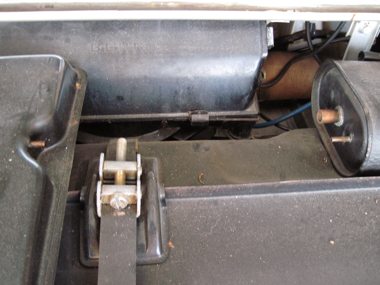
I have two hydraulic jacks, as you can see below.  We used a furniture dolly and two 2x4s, and brought the jacks up to just take the weight of the engine + transmission.


I removed the two bolts holding the engine brace, then the two nuts holding the transmission, and in 5 minutes the engine is no longer attached to the car.  The plan was to drop the front by a few millimeters, then the back, then the front, etc.  That worked well for an inch or so, but then the front jack lost its lock and slipped all the way down.  We tightened it up and jacked it back up about six inches.  We then dropped it evenly until the back jack was down as far as it would go.  We let the front down all the way, then brought that jack around to take the load off the back, then gently let the back down.  Whew!  Would have been better to have two of the blue style jacks, but it worked out.

A final issue popped up - even with the car up on jack stands, the car body was a few inches too low to roll the engine out.  We thought about using the hydraulic jack to raise each side and get a few more clicks on each jack stand, but that would involve a stack of 2x4s to get the needed height and I wasn't comfortable with that.  Then I remembered we had just taken several hundred pounds of the car, so I walked around to the back and lifted the car up.  It actually went up a few inches, so Fred raised the jack stands on each side as I lifted.  That gave us the extra space we needed.  I carefully rolled backwards, maneuvering around the driver's side axle and the tubing on top.  And here we are!


The engine and transmission are strikingly big for the place where they fit in the little car - hard to believe the clever Germans actually fit it all in.  Here's the big empty space from above and below.


We still had some light left, so we decided to pop the transmission off the engine.  I'll reuse the flywheel, clutch and transmission with the electric motor.  That way I can shift it like a normal car if needed.  There are four bolts holding the transmission to the engine.  We got three of them off easily, but the head of the fourth bolt was obscured by where it's located on the starter motor flange, and we couldn't get a socket or open-end wrench on it.  After some creative metalworking (because I won't be reusing the starter), we got the bolt out but discovered that this bolt is very long, and goes all the way through the engine mount to an exposed nut.  All we had to do was back the nut off from the other side.  Oh well!  We wiggled the transmission a little and it separated from the engine.  Fred supported it while I pulled them apart and it came off easily.


Next step is to take the pressure plate, clutch disc and flywheel off the back of the engine.  The pressure plate came off easily, after we jammed a 2x4 into the teeth of the flywheel to stop it from spinning.  I got some repair receipts with the car that show that the clutch was replaced in the past, and both the pressure plate and clutch disc look great.  They're both about .375" thick - I'll have to check to see how that compares with new, or if they should be replaced while I'm in there.  Also, they're both clean and dry - no sign of oil leaks that mean that they're ruined.


We tried to work on removing the flywheel, but the 5 bolts holding it on the engine just didn't want to release, even with my cordless impact wrench.  We gave it a good spraying with WD-40 and wrapped up for the day.  Probably my most productive day so far, and a lot to show for it!  I'll have to do some checking to see if there's a trick to get these bolts out.  I'll probably need to lock the driveshaft somehow.

Saturday, December 12, 2009

Suspension and Brakes Result, CV bolt tool

The good news is that the brakes had been upgraded to the BMW parts by a previous owner, and no further work on brakes is needed.


The bad news is that the shocks are replacements, but they and the springs are factory spec, and definitely need to be upgraded.  Electro Automotive sells upgrades as part of the conversion package, so I will have to go ahead with that.

It turns out that Pelican Parts can no longer supply the 12-point CV joint bolt removal tool, so a quick Google search led me to MetalNerd.  They specialize in German car tools and accessories.  The order was handled very quickly and I got it in my hands in two days!  Fred's coming over on Sunday and we'll get the engine dropped.

Sunday, December 6, 2009

Bumpers and Interior Removal, Brakes and Suspension Check

Yesterday I removed the front and rear bumpers.  Very straightforward, no surprises.

Today I worked on pulling the interior.   Some easy, some tricky...

First I pulled the two seats, with four bolts each.  Then I worked on pulling up all of the carpeting.  First I removed the defroster light fixture, then loosened the small setscrews holding the shift knob on, then pulled up the center hump carpet.  Then it got tricky because the steering wheel shaft goes through a hole in the carpet, so I had to unbolt the U-joint just above the carpet hole.  This was tough as the shafts that come into each side of the joint are quite long.  I ended up unbolting both sides, then prying apart the upper fitting until I was able to slide it up far enough so it came off the lower shaft.  After that the carpeting pieces came up nicely.  Then I removed the seat back panel and the aftermarket 3-point racing harness seatbelts.  All of this work led up to the gutted interior.  I found a dollar bill and about another dollar in change, so the car is trying to offset the cost of this project!


Next I moved on to the steering wheel.  I recently bought the required 27mm socket.  I quickly realized that the nut was on very, very tight and I had trouble trying to hold the wheel and undo the nut.  I finally stuck a 2x4 through the wheel spokes and jammed it down into the passenger wheel well.  When it finally let go, it was easy to get off.  Then I removed the indicator and windshield wiper controls.

With this pulled, I can see the source of two problems I was having.  First, the copper strips that conduct the signal for the horn switch are actually worn through.  So those have to be replaced.  Second, I found that the auto-return mechanism for the indicator is broken.  There were a couple of broken pieces of plastic in the area, so I'll have to see how that can be fixed.

Next I thought you'd like to view the heart of the device that is insanity that is the spare-tire-pressure-driven-windshield-washer-system.


If you zoom in on the picture, you'll see a little black tab that goes into the in-and-out fluid connectors.  When you pull on the windshield stalk, this black tab is pressed into the fluid connector, allowing the fluid to flow.  Unfortunately, it's bat-shit crazy engineering.  I have a couple of choices - I can just leave this alone or remove it and mount a push button switch on the dashboard, or I can track down a 924 windshield control stalk that has an electric switch to drive the washer pump I bought.  I'll make the decision later.
Next I checked the springs and struts.  They don't look original so I may be in luck here.  The springs are .388" thick, so I'll be able to find out what load they can handle.


I'll confirm both of these upgrades with my contact at Strasse Porsche in San Luis Obispo on Monday.

Sunday, November 29, 2009

Engine removal first steps

With the gas tank gone, there is no going back to an internal combustion ride!  I began to follow the Haynes manual process for engine removal.  It said to remove the hoods, then the battery.  First actual work on the engine is to slip off the air hoses and remove the air box.  Here we are at that point.


You can see on the far side that the "hell hole" around the battery has been previously worked on, but the rust was building up again on the battery holder itself.  Time was right to get this fixed anyway.

In a clear case of "The solution is left to the reader", the Haynes manual says "Working logically, detach the electrical leads which go to the engine from the various looms."  Uh yeah, thanks for all of the detail.  There are 2 major wiring harnesses: the fuel injector computer and the high voltage to the starter motor on the underside of the engine.  Here's the fuel injection computer harness:
 

Next, the Haynes manual says "Working logically, detach the various vacuum and fuel hoses from the engine."  Awesome.  So, with this completed, the engine is only held into the car via the underside greasy bits.


Getting underneath the car, I removed the ground strap, the speedometer cable, the clutch cable and pulley, the gearshift rod and the heater boxes and tubing.  The next step in the manual is to remove the driveshafts, but in a stroke of bad planning, I didn't order the special 12-point star bit needed to pull off the CV joints.  With a few more hours of sunny and cool Sunday, I decided to pull the exhaust.  I had initially thought to leave it attached so I can sell the engine and exhaust as a single piece, but getting underneath and looking at it, I decided it would be a good idea to take it off while I had the chance.  The headers and muffler look nearly new which is great, but whoever put it on really didn't do a good job - there were several missing screws and bolts, and one of the sheet metal heat guides wasn't even attached!  It was just jammed in place and probably banged around on every bump.  One big issue was a missing bolt on one of the exhaust ports!  I don't know if it's the way it's designed, but there is no exhaust manifold gasket at all.  The fit is tight, but not perfect so I suspect there was a lot of blow-by.


So I ordered the star bit from Pelican Parts and expect to drop the engine next weekend.

Up on Jack Stands, Hood and Gas Tank Removal

Up to now, the car was still driveable.  Time to commit to the destruction!  First thing to do is get the car up on the jack stands.  I used my hydraulic jack to lift up the front driver's corner.  I want to put the jack under what seems to be a reinforced metal ring just behind the wheel well.  I used a couple of pieces of wood to spread the weight load and got the jack in place, at its lowest height.  The car is so small that lifting it this high brought the other side of the car right off the ground too.  I went back to the rear driver's corner and lifted it at the metal ring, with the goal of putting the jack stand under the thick pivot arm of the rear suspension.  The jack stand has a U-shaped top, so the pivot arm fit perfectly.  I then went around and did both corners of the passenger side.  It looked like it wasn't high enough, so I made another pass around the car, jacking it up several more inches.  And here we have it!  I can now comfortably roll underneath with my creeper, and there is sufficient room to drop the engine.


Next came the removal of the front (bonnet) and rear (boot) hoods.  This gives complete access to everything that happens from this point on.  The hoods are only held on with 4 bolts onto the spring-loaded arms.  I think I can leave the front arms in place but the rear arms had to come out.  They're only held on with one bolt, but there is a lot of spring pressure, so be careful when they're about to come loose!


Now onto the main event, the removal of the gas tank.  It's pretty straightforward.  First I had to drain the 5 gallons or so of remaining fuel.  I bought a cheap siphon with a primer pump and it took about an hour.  If you can, get something that will do the job faster.  Also, the hosing wanted to keep its rolled-up form, so I electrical-taped it to a straight stick I found and stuck it straight down the filler hole.  Luckily this got nearly every drop out.


Then it's a matter of removing the spill ring and expansion tank bolted to the top of the main tank.


Then the strap across the tank and the fuel level sender cable connector are removed.  At this point, the tank is only in place via two hoses at the bottom.  Ignore what the Haynes manual says, and don't bother removing the stone shield under the tank.  It's not necessary, and one of my bolts was seized anyway.  You can lift the tank up from the passenger side and slide the two hoses off their pipes.  If the won't slide easily, cut them off.


And we're done!  This is the hole where the gas tank was, and where the electron tank (batteries) will go.  If you look closely, you'll see a shiny metal bar going across the front of the area.  That's tied to the front suspension on both sides so I suspect it's an aftermarket torsion rod.  No wonder the handling felt very tight and stiff!  I just hope it doesn't interfere with the placement of the battery holders.

Odometer Repair

As soon as I drove away from buying the car, I realized that the speedometer worked, but the odometer and trip odometer didn't.  Since there's only one cable into the gauge and the speedo worked, I knew the odometer problem was inside the gauge itself.

Going by an article on the Pelican Parts web site, I knew I needed to get inside and check for a slipping gear on the main shaft.  The trickiest part is getting the gauge open.  It was clearly never meant to be opened because the metal ring around the gauge is bent around from the front to the back, holding everything in.  You have to carefully bend the back of the ring away from the housing.  A small screwdriver and a lot of patience is required. Go a little more than halfway around the gauge, prying the metal ring about 1mm, then go back and do more passes until the ring comes away.


Now that you have the front open,  remove two small screws on the back and gently remove the mechanism.


There are two parts to the mechanism - the gearing at the back and the mileage wheels at the front.  Don't mess with the wheels or the speedo needle if you don't have to - the wheels are a bear to put back together and you'll have to recalibrate the speedo if the needle moves on the shaft.

I played with the gearing mechanism a bit by hand and realized it was going to take a long time to get the dials to spin.  Then I realized that the trip odometer reset cable actually fits perfectly into the main speedometer cable jack.  I looked over at my drill and figured it could spin the cable faster than I could by hand, so I hooked it up and pulled the trigger.  Looks like my drill tops out about 110 mph!  I then saw that both odometer dials spun properly!  Argh!  I don't know what I did, other than making sure the gearing was all seated properly and turned things by hand.  It will suck if I put it back together and the odometer doesn't work again.  Since I'm diving into major demolition, I'll put the completion of this little project on the back burner.


Sunday, November 22, 2009

Plans for the battery management and gauge system

People might think that electric car conversion is a bleeding-edge activity.  Not so!  I fact I'm going to leverage some hard work done in the past with some futuristic technology for my battery management gauge system.

First, we start with the PakTrakr.    I don't know why they hate the letter c so much; must have had a bad Sesame Street experience...  This device measures the voltage on each battery in the system, battery pack temperature, current draw while in use and alerts when any reading goes out of spec.  These are all of the values you need to know your % of charge and, after a few trips, your full-charge driving range and remaining driving range.  The unit comes with a dashboard mounted display that does the job, but screams out for a sweeter display.


Where the awesomeness really comes in, is the PakTrakr has a serial port output.  It spits out a CSV (comma separated values) data stream each second, with all of the relevant data.  If I had a computer of some kind that read the data and displayed some graphs, that would be perfect.  I did some investigation of "car PC" equipment and found most people go for a tiny PC with an LCD display.  Of course, these car PCs normally have music, GPS, video, cellular telephone and other features included.  I wasn't sure I wanted a dedicated, expensive device so I started thinking about using one of the new generation smart phones as my computer.  Most phones have a USB connection and I can easily convert the PakTrakr's serial cable to USB.  Writing an app that reads the USB port, parses the data and displays the graphs gets me what I want.  There is one downside - I would have to plug the USB cable in each time, and hack the wire to deliver +5V to keep the phone charged.  I suddenly realized that smart phones have a wireless Bluetooth facility, and I found serial-cable-to-Bluetooth adapters on the web.  So all I need to do now is to write code that reads the Bluetooth connection, and I don't have to be hardwired into the car!

Now what phone to get.  iPhone is the obvious choice due to market popularity, but frankly there are a couple of problems writing apps for the iPhone.  First, you have to develop your code on a Mac, nothing else.  I don't have a Mac or Mac development skills, but I'm willing to leverage my Java skills to get me where I need to be.  The second problem is the bizarro-world of iPhone app approval.  I don't like the way Apple is handling this, in typical mysterious we-know-what's-best-for-you style.  So iPhone is out.


This leaves an Android-based phone.  Android is Google's open-source Linux-based smart phone operating system and development platform.  The whole operating system is completely open source, apps are written in Java, and there is no "approval process" for apps that developers write.  Sounds like this solution is for me!  There are several Android-based phones on the market now, and the latest is Verizon's Droid phone.  I played with it at the store the other day and it's just beautiful and feature-packed.  I installed the Android 2.0 development kit and there is support for reading Bluetooth serial port sockets.  Now I just have to switch from T-Mobile to Verizon, sign up for the plans and get a Droid.


The heart of the code will be parsing the PakTrakr's CSV data stream.  I read about Doug Teeple's Sharp Zaurus project where he did the same thing I want to do, but on an older PDA device.  Doug's web site shows off his Karmann Ghia electric car conversion efforts.  In the spirit of community I emailed Doug and asked him if he would be willing to accelerate my development by contributing his CSV parser code he's already written.  He quickly wrote back to say he would do so.  It's in C, so I'll easily translate it over to Java, and then write the rest of the app around it.  I will make the final application and all of the source code available for free download here. Stay tuned for updates in this area.

Monday, November 16, 2009

Wrapping up Preliminary Body Work

This weekend was spent grinding, sanding, filling, sanding and priming the paint chips and rust spots around the car.  First up is the cowl area on the passenger side that I worked on last weekend.  I dug out the rubber strip that was stuffed in the seam between the fender and the cowl.  It was moderately rusty underneath so I sanded the crack and slathered in Rustoleum.  I then sanded and primed the whole area to prevent new rust forming on the bare metal.


Remember I previously said there were no more Mystery Holes?  Well I found the last two.  They're located at the bottom of the front fender panels, directly below the rusty mess of the cowling.  There's clearly a failure mode of water not draining properly in these areas.  I could see filler and primer in both areas, with a bit of rust poking through.  I dug out the filler and rust down to good metal, sanded, Rustoleum'd, then primed.  With 5 areas needing metalwork, I've come to the conclusion that I'll let a professional shop restore good metal into those places.  I don't want to do all of this work, then fill the gaps full of body filler, which is I think what happened previously and got us into the situation we are now.  I'll let them work on welding new metal into place, then apply some super-rust preventive technology.

Here's the driver's side before and after:


and here's the passenger side:


I also did several surface rust spots and paint chips around the car, wrapping up what I can see of the bodywork.  Here she is in all of her glory, covered with paint masking paper.  I'll let the primer cure and spray with silver paint next weekend.  This is not the final painting, just a temporary coat to get me through the rest of the restoration.  In the course of getting to this point, I've removed a bunch of trim chrome and rubber.  I'll get recommendations on restoration and painting shops, then talk to them about the project and what they need me to do to the car to optimize the process.

Tuesday, November 10, 2009

She's Giving Up Her Secrets

Well I don't know if the car is a she or a he yet, but the secrets are slowing being revealed!  After digging out the Mystery Hole behind the passenger door, I decided to dive into the clearly worked-on place on the driver and passenger side where the cowl meets the front fender meets the A pillar at the corner of the windshield.

A bit of bad news...  As I was removing the chrome trim from around the windshield, an inverted L-shape crack appeared in the windshield.  It's about 6" on each leg of the L, so the windshield is likely toast.  I did a quick Internet search and new windshields aren't too expensive.  I was going to remove the windshield for the new paint anyway, so this just reinforced my decision.  I won't be doing any serious driving so I'm not worried about a catastrophic failure.

Now on to the mystery spots.  First, the "before" pictures.  Here's the driver's side:


and here's the passenger side, after a bit of grinding:

So what can we spot here?  There's primer over body filler.  There's rust showing through.  The body filler is cracked where the cowl body panel meets the front fender meets the A pillar.  Sigh.  OK, let's dive in with grinders, palm sanders and my woodworking 1/8" long-shaft chisel (the handy tool that dug out the Mystery Hole).  Here's the result on the driver's side:


So what did I find?  Filler stuffed into the seam between the panels.  I dug all of that out and found several layers of  filler.  Under that I found a rusty hole, and the sides and the bottom of the seam itself was Swiss cheese.  This will be interesting to repair.  I've brushed on Rustoleum everywhere my tiny paintbrush will reach, so that will halt the accessible rust.  I'll need to figure out how to get strong metal on both sides of the seam, seal up the hole and some small penetrations near the windshield and up the A pillar.  What you can't see is just below the visible part of the picture was a rust spot about the size of a quarter, that pushed proud of the rest of the panel.  I knew that meant rust growing under the paint, and as I dug it out it was clear it had rusted through from the back.  Since this hole is about 6 inches below the hole you can see above, there's likely more rust action on the inside of the fender panel.  I'll take a closer look behind next weekend and see what I have to do to halt the rust and repair any issues.

Now over to the passenger side:

Whew!  Not as bad as the driver's side.  No penetration, but a bit pitted from the top.  Also notice what appears to be a rubber strip inside the seam between the panels.  The driver's side didn't have this, it was packed with body filler.  I'll have to do some research to find out what this should really look like, and do it on both sides.

Next I found the clearest evidence that the top layer of paint was a cheap respray.  This is the windshield wiper motor mount.


That's silver paint peeling off silver paint.  This is the only place I've seen peeling, but there is other evidence of the respray so I'll have some work to do to properly prep the car for the new coat of paint I'll be arranging for it.

The good news is there are no more mystery spots!

Saturday, November 7, 2009

The Mystery Hole

After the dashboard, I decided to go back and attack an "interesting" aspect of the bodywork.  Just behind the passenger door is an area that clearly had some work done, and not completed.  I could see primer paint and some body filler underneath.  I put the wire wheel on the drill and started to grind off the primer and rust to get down to good metal.


I got to the point where I saw some white material underneath, so I stopped and poked at it with a screwdriver.  To my surprise it had some give to it, so I dug a bit out.  It turned out to be white acrylic bathroom caulk!  Instead of properly welding in a small piece of metal into the rusted area, somebody decided to squirt about two cups of caulking into the hole, then top it off with filler and primer.  It took me about half an hour to dig out all of the caulk.


I'll treat the remaining surface rust with Rust Reformer.  I'll work with The Sheet Metal Shop guys across from where I work to get a replacement piece fabricated, and then Gary from G-Rides will weld it in for me.  I've got a couple of other suspicious areas that I'll dig into and then we can take care of everything at once.