Sunday, November 27, 2011

Battery Box Vent and Windshield Washer Redux

The EA plans for the mid pack battery box exhaust call for drilling a big hole in the passenger-side front wheel well.  I've been dreading making that hole and now that I'm at the end of the project I need to do something to get rid of the hydrogen generated during charging.  The position of the hose and hole drove me to get rid of the original windshield washer tank and install a small tank on the back of the mid battery pack.

Today I had an epiphany.  I was down under the car and noticed a large hole in the bottom of the body right below where the gas tank used to be.  The hole actually opens into a protected area where the steering rack lives.

I started by running an exhaust tube from the battery pack's fan port down to the hole.


I anchored the bottom of the tube to the brake line.  Not the cleanest thing in the world, but will suffice for our needs.  I have the leftover tube mount bracket so I'll see if it's viable next time I get a chance.


This gave me the room I needed to mount the original windshield washer fluid tank back in its home, and run the output tube to the new electric washer pump.


And the beauty is I got windshield fluid squirting out both jets the first time I tried it!  This meant that the replacement 924 electric actuator lever and new electric pump worked just as I planned.  I'm happy I was able to ditch the ugly but functional fluid tank and go back to the original.

Even though the tank cap looks like it's in a low position, I was able to get a lot of fluid into the tank.  I don't plan on sealing up the hole for the spare-tire-pressure-hose, as it will act as a pressure equalizer.

Auxiliary Battery Disconnect

The EA kit just has you bolting multiple ring connectors to the positive and negative terminals of the auxiliary 12V battery.  As I was working on different systems on the car, I had to bolt and unbolt over and over.  I realized that this was really inconvenient and also possibly dangerous if I needed to disconnect the battery in a hurry, like in a crash or fire.  Since I had used an Anderson connector on the charger output, it made sense to do the same for the auxiliary battery.  I crimped all of the incoming and outgoing wires into the connector pin to make everything nice and clean.  Oh and I put wire loom on everything in sight!


PakTrakr Next Steps and USB Device Power

With the PakTrakr remotes installed and tested, it's time to add the current sensor.  The opening in the sensor is not big enough to pass a lug or battery cable through, so I used the copper bar provided in the kit, and bolted it in.  The sensor's data cable runs through the firewall and in behind the dashboard for its ultimate home in the PakTrakr dashboard display unit.


With that done, it's time to clean up the wiring.  Each PakTrakr remote has a generous amount of wire to run to each battery.  With the help of some butt terminals and zip ties, the wiring is now nice and tidy.

Here's the front battery pack.


Here's the mid battery pack:


Here's the rear battery pack:


and here are the saddlebags:


The final component to go into the PakTrakr system is the serial port output cable.  I've got it lined up here next to the serial port Bluetooth transmitter device which provides the path to the Bluetooth receiver in my Droid Bionic.  This delivers the data stream from the PakTrakr to the Android app I'm desperately trying to finish up, which will run in the phone as I drive down the road.


The Bluetooth transmitter needs power and conveniently it will take power via a USB cable.  My Droid Bionic also will take power via a USB cable.  I also plan to mount a GoPro video camera which recharges with USB power.  See a pattern developing?  With three USB devices, I looked around for a USB hub with 4 ports (for future use or passenger's device) and high-power delivery a la USB 3 at 900ma.  It has to take 12VDC so I don't have to have a separate power regulator.  I came on this sweet device, the awkwardly-named USBG-3X4M.  Notice the green 12V power connector.


Here it is mounted up under the dashboard.  The BlueTooth transmitter powers up no problem, but my Droid Bionic won't recognize any power coming from the unit, no matter what USB cable or port I try.  I've emailed the vendor and hopefully they'll have a suggestion.

CalPoly Electric 911 Project

I went to the local Porsche Club New Member BBQ a few weekends ago and met up with CalPoly students in the Motor Car Association who were recently given an electric-converted 911, in baby blue...  The downside of the project is the current  range is somewhere around 100 yards!


The students built a really great display.  They're looking for assistance and donations to restore, upgrade, learn a lot and get it out on the road.


The bad news is the 10 12V lead-acid batteries are toast.


The good news is it's got a Zilla ZL-1 controller!  There's a lot of potential there with the right battery pack.


 The original owner had some good ideas, including 4 contactors!


I was approached by Bruce Bero of the Porsche club, as I'm the resident "expert" on electric cars.  The club has agreed to assist the students and the project in whatever way we can.  The first bit of guidance I gave to the team is to ditch the batteries for a set of Lithiums (LiFEPO4) if they can get donations.  The controller, charger and motor are all good, so the batteries are the natural starting place.  I pointed them to the video archive at evtv.me to get a deep dive into electric cars and battery technology.  I'll stay in touch and help them as needed.

Sunday, November 13, 2011

Checking out the charger

After the success with getting the motor turning, I moved to the charger.  It was all wired in, I just needed to plug in the heavy 120V extension cord and see what happens.


Success!  The red light shows it's in the startup phase of the charging cycle.


The temperature probe is deep inside the junction of 4 batteries in the front pack.


Here's a view of the charger in action.  Note that the charging system cuts off the 12V to the rest of the car and the state-of-charge gauge goes offline.


The battery box fan circuit came on, exhausting the hydrogen generated during charging.  Each battery box has a fan and a duct to the outside.


The DC voltage pushed out of the charger started around 139V and peaked at 148V.
 

I put my Kill-A-Watt between the wall plug and the charger cable.  It was dark by then but you can see it's pulling 14.64 amps...


for a total of 1262 watts.  That's a good size microwave or hair dryer.  Next time I do a full charge I'll get it to give me the total kilo-watt-hour (KWH) count of energy pulled.  This will help me estimate my yearly energy draw to see the impact on my solar power system.  I currently make about 80% of the power I use, so adding car charging will drop that down.  I have a clever plan to add a solar carport over my parking area.  This will shade the cars to keep them cool in the blasting heat of the sun, plus make some additional solar power.

Saturday, November 12, 2011

It's Alive!

Well today was the big day.  After the "Scary Spark Incident", as it became known, everything was wired up and ready to spin the motor for the first time.  This post is going to be mostly video for obvious reasons.  I hope you've got a good Internet connection.  Enjoy!


So it turns!  All of that work finally came to fruition.  I was a bit worried about the way the Curtis 1231C motor controller wiring is documented in the EA manual - nothing hooks up to the A2 terminal, which doesn't make any sense to me but EA must have thought out and tested their design.

But what's up with the scraping, scratching sound?  Turns out the transmission was actually in gear and the hubs were turning.  It sounds great in neutral.  And of course when I say engine I mean motor...


Now to do a test with it intentionally in gear.  The sound is much better due to the surface rust being rubbed off the brake rotors.  When I say I disconnected the throttle linkage, I actually mean I disconnected the shifter linkage.  I was moving the gear linkage pivot right at the side of the transmission, so I really don't know what gear I was selecting.


Now that we've tested reverse, we need to find a forward gear to check that the motor is wired to turn in the correct direction.


And then select another gear to confirm forward.


I spent the rest of the afternoon wrapping wires in wire loom and zip-tying up the big 2/0 cables and making sure everything was securely fastened to avoid noises and not rubbing against anything bad.  It was a great day.  :^)

PakTrakr wiring

It was time to install the PakTrakr remote units to the battery pack.  The key to understand is the PakTrakr "Battery 1" is the most-negative battery in the set to be measured by the remote.  The black wire goes to the Battery 1 negative terminal, then the voltage sensors wires go to the positive terminals of Battery 1 up to Battery 8, with color code Red, Green, Blue, Orange, White, Brown, Yellow, and Violet.


Since the PakTrakr remote pulls a little bit of current all the time, I put a detachable link on the Black wire.  I'll pull them if I won't be driving the car for a while.

As soon as the Black and Red wires were connected, a small greed LED started blinking on each remote.  This indicates that the remote is working correctly.  I'll clean up the sensor wires with small zip-ties once all of the data checks out.

The next step will be to daisy-chain each remote's data cable back to the display in the dashboard.  I'll then install an RS-232 to Bluetooth adapter which will drive data to the app on my Android-based Bionic.  I just upgraded the phone a few weeks ago - it's got a faster CPU and more memory, but most importantly it has a bigger screen for better visibility of the app display.

Batteries and Sparks!

Well it's over a year since I started the project and today I put the batteries into the car!  I just want this to be over so I drive the car...

I loaded them one by one and they're very heavy!  I bought a rubber loading strap from the battery place which hooked into the two plastic brackets molded into the top of each battery.  I had to be careful not to bang them into the body or drop them, and everything turned out OK.  Here are the saddlebag batteries.


And this is the former engine bay.


This is the former gas tank area.


This is the former front trunk / spare tire area.


Here's the full front area with the charger in place.


 I then started hooking up the battery bus bars.


I put all of the battery bus bars in place as a mockup and found that there was one missing!  Another final insult from EA!  I had to buy some copper stock but the best I could find was too thin, so I had to double-up.  I had to get some 1" shrinkwrap too.


Measuring and bending the double-thickness was difficult to get right.  I had to put the shrinkwrap on before I started bending the second end.


And it's complete, short of a little fine tuning.


Here it is installed, looks almost factory-stock.


The last missing piece was a copper bus bar going between the two bottom terminals on the motor.  I thought about making it out of a small piece of leftover 2/0 battery cable and two lugs, but since this is going to be exposed to the road, I decided to build it the way EA would have, if they had shipped it to me...  And here it is.


Here it is bolted to the bottom of the motor, just like it should have looked.


Next I bolted up the bus bars in place to all of the battery posts.  I then followed the directions in the EA manual and checked the voltage of each battery bank, and everything looked good.  The last connection to make was the most-negative battery's negative terminal to the most-negative post.  This is where it got exciting...  I touched the lug to the terminal and it made a big spark!  The manual didn't say anything about that and I was worried I had a short somewhere.  I started unbolting the cables between the battery racks and checking voltages and grounds.  I couldn't find the problem and it was getting dark so I figured it was smarter to sleep on it.

I decided to check in with the accumulated knowledge of the 914 electric conversion world on the 914EV newsgroup.  Here's my post:
As I mentioned in the previous message, today I was going to make the
motor turn for the first time.  I had all of the battery bus bars and
cables attached, except the final connection from Battery 14's Neg
terminal to the most-ground post.  All of the partial-pack voltage
readings matched the manual's checklist.  When I went to put the final
lug on the mount-ground post I got a big spark, which I assume is a
short somewhere.
I started trying to narrow down the problem by isolating the battery
boxes, removing cables from battery terminals, the controller, the
motor, the contactor.  I couldn't get rid of the spark.
In frustration, I put my meter between the battery and the most-ground
post and found I had a current draw of 0.3A.  Not really much, but
enough to make a spark and make me think twice about proceeding.  This
is with the aux battery disconnected, the DC-DC disconnected, the
motor disconnected, key off and breaker off.  None of the car's 12V
features are on.
The only thing out of the ordinary is a PakTrakr system, with a
voltage sensor wire on each of the 20 batteries.  I disconnected each
PakTrakr unit's power supply wire and the LEDs all went dark.  Even
when powered up, the PakTrakr should pull no more than 32 mA, and I'm
seeing about than 10x that.
I got several great suggestions back almost immediately.  The gist of the problem is the spark was from the current draw on the big capacitors in the motor controller.  The next morning I was convinced it was the source of the problem by holding a heavy-gauge jumper wire between the cable and the battery terminal.  I held it there for 1 minute, took it off and touched it again and there was no spark!  I bolted the terminal in place and everything was good!

Next up, wiring up the PakTrakrs and the first attempt at spinning the motor!

Saturday, November 5, 2011

Fuse Block #2

Alert readers will remember that I decided to install a second fuse block.  The replacement fuse block is great, but it's an exact swap of the original.  I'm adding a bunch of extra circuits and don't want to overload the existing wiring.

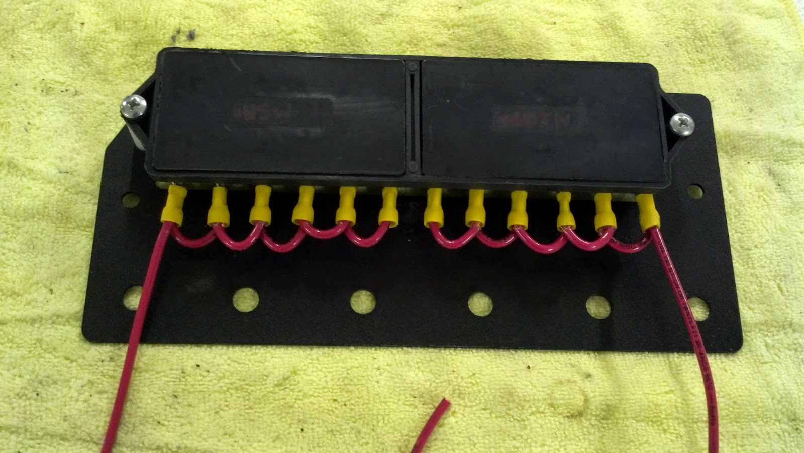
Here you can see that I installed jumpers to make half of the fuse block to be constant-on 12V and the other half to be switched.  As these are the feeders, I used heavy gauge wire.  The switched wire is the short one below, it goes over to the first fuse block and picks up the switched circuit.  The unswitched wire goes all the way back to the 12V auxiliary battery terminal for the cleanest power source.


Richard Rodriguez warned me about poor grounding that he found during his conversion, so I cut the big, fraying, single-gang grounding bundle of brown wires into several smaller ones, crimped on connectors and heat-shrink tubing and secured them down on the grounding bolt.


I drilled and bolted the second fuse block into the first one, and it was a very tight fit!


The one thing I didn't count on was the position of the battery circuit breaker.  The downside is I lose a couple of the unswitched fuses.  The upside is the back of the breaker's housing holds the second fuse block securely in place.  This will all look better when I install the carpet and tidy up the wiring.

A Leaf in the Wild

I was driving by the Rabobank in Atascadero and decided to check on the charging station there.  I was glad to see a Nissan Leaf hooked up and charging!  I left one of my project cards and wrote "Congrats on the Leaf!" on the back.


The station has a sign explaining that it was installed as a joint venture by Solar City, California Air Resources Board, Rabobank and Tesla.  The goal was to build a series of charging stations between San Francisco and Los Angles.


Here's a closeup of the sign and the Tesla-branded charger.  I believe the charger has been retrofitted from the 2009 model to the recently-introduced J1772 connector.
 

EA Gauges

The kit comes with ammeter and state-of-charge gauges.  Unfortunately they gave me a 3-hole mount and only 2 gauges - typical!  I bought a chrome 2-hole mount from a local auto parts store, then sanded, primed and painted it black.  I mounted the gauges in the holes, the followed the directions to install and wire the backlights.


I did a temporary mount of the assembly to the underside of the dashboard, then wired them up to the battery pack, current shunt and 12V supply.  This will give me a good indication of what's going on with the battery pack if I don't have the Android app running.

Wrapping up the Windshield Washer System

Alert readers will remember that I upgraded the windshield washer control stalk from the fluid valve in the 914 to the electric version from a 924.  I also added an electric washer pump motor.  The last thing required in the system is a washer fluid tank.  The original washer fluid tank wouldn't fit into it's home anymore due to the fuel-tank battery box.

The local O'Reilly Auto parts place had a selection of plastic tanks intended for radiator overflow, and one was small enough for my needs.  It attaches with a spring clip.  After testing it in several places it looked like the best thing would be to attach it to the back of the battery box.  I carefully measured and marked, then installed some rivnuts in the battery box wall.  I had to grind down the back of the rivnut and the bolt as they were impinging on the space needed by the battery in that corner.


And here is the tank in place.  I ran tubing out the bottom of the tank and looped it around and into the input of the washer pump, making sure the bottom of the tank is above the pump to keep it primed.

The hole in the tank is in a very convenient location for filling.  Job done until I can test after final pump wiring hookup.

Wrapping up the Brake Pressure Switch

Alert readers will remember that the connectors I attached to the ends of the two brake pressure switch wires were too long to be covered nicely by the rubber cover I bought.  The key was to get some right-angle connectors, crimp them onto the wires, press the connectors onto the switch terminals, push on the rubber boot, then use high-quality tape to waterproof the whole schebang.  And here we are!

Tach sensor

The Electro Automotive kit comes with no provision for a device to collect motor RPM data.  They do have the tach wire terminate on a block in the rear contactor area.  While I was at EVCCON, I saw the WarP Speed Sensor from ReChargeCar.  The picture I took of my unit is horribly out of focus, so I've copied the one from the ReChargeCar web site.


The speed sensor is a simple but effective and flexible tach sender.  You see the 4 setscrews in the ring?  Those are removable in case your tach requires 1, 2, or 4 pulses per rotation.  I left all 4 setscrews in place until I get the motor running, and I'll be able to adjust it if the tach reading isn't correct.  Here you see the ring with the sensor bolted to the front end of the motor.  The sensor can be adjusted closer and farther away from the shaft, but I left it at the factory setting.  I'm very disappointed that my motor shaft is rusting!


And here is the ring, tightened up to the shaft.  The setscrews fire the sensor as the ring spins.


 Finally, I wired the sensor's cable to +12V, Ground and the tach wire.  Can't see if it works until the motor turns for the first time.