This blog follows the progress of restoring and converting a 1973 Porsche 914 from stock to full electric drive, with an electric motor and half a ton of batteries. Now that the car is done and in storage while I live overseas, I'm adding descriptions and pictures of each Tesla location I visit.
I spent the afternoon of my birthday playing around with a new Lithium ion battery pack design for the 914, if I ever return to civilization.
To save money and complexity, I'll keep the existing Curtis 1231C-8601 controller which is rated for a maximum 144V pack and 500 amps. This is still sufficient for me driving through town.
Based on years of experience at EVTV with the China Aviation Lithium Battery Company (CALB) 180AH CA-series cells, I know how to bottom-balance them, charge them and discharge them safely. This is in deference to the many YouTube guys building up Tesla-like 18650 packs from dodgy laptop battery packs. I did the math to determine I need 42 of the CALB cells at a nominal 3.4V each.
I brought up an old SketchUp model I made a couple of years ago and worked out how to place these batteries and other components. I'll fill up the rear battery box where the gas engine used to be and put the rest in the battery box where the gas tank used to be, with a good amount of space left over.
This means I can remove the 2 single-battery-sized boxes from the trunk and weld some steel plates into place, prime and paint and turn it back into a fully usable trunk.
I also gain all of the capacity of the battery box where the spare tire used to be right in the front. I created shapes matching the sizes of the rest of the components I need and fitted them all into place. This means the new TCCH 4KW or 5KW charger I'm looking at and its controller, the new GEVCU controller, the existing relay board and the existing DC-DC converter all fit inside the front box. The TCCH is air cooled but the box already has an exhaust fan that switches on during charging, so it looks like it will be a perfect setup.
Cleverly I'm moving the 12V auxiliary battery from it's ugly, nasty, breaking-off-prone mounting bracket on the front of the front battery box to inside the gas tank battery box due to some newly available space. I'll run the 12V wires down the passenger side of the frunk to the DC-DC controller and leave the high voltage battery pack wiring where it runs now down the driver's side. There's even still a bit of empty space so I'll play with the position of the batteries to maintain side-to-side weight balance and fill the gaps with some stiff foam.
So, here's the layout. I've also built up a list of to-do items, some must be done concurrently with this major upgrade, while the rest can be done at my leisure. I'll bling up the installation by replacing the white plastic battery pack lids with transparent lids.
Day 2 kicked off, surprisingly on time, with John Hardy from the UK. John returns again as our overseas battery testing expert. He reviewed his earlier battery testing methodology and cell types.
The Headway 38120S cell had no detectable voltage drift but the first cell failed after 600 discharge / charge cycles.
He tested a shunt balancing product which simply destroyed the pack in under 100 cycles. He is a fan of bottom-balancing your pack before assembly.
His CALB CA40fi cells lived beyond 2000 charging cycles and each of the 8 cells showed nearly identical voltage profile on the 2000th cycle, which is exactly what we want in our batteries.
John's full testing history shows that Lithium Ion batteries have no discernable drift and an extremely long charging cycle life.
John then moved to his current (no pun intended) testing of the Tesla-style 18650 LiFePO4 cells. He has developed a new charging algorithm so has asked us to not talk about his ideas until they're protected. I will say it's very sophisticated and looks very good! Hoping to hear good things in the future.
Session: Collin Kidder – CAN Bus Hacking Hardware And Software
Collin's work writing software to collect and analyze CANbus traffic of existing OEM automotive components has formed the cornerstone of the reverse-engineering innovation of the world-wide EVTV team. Due to his efforts we now can control the charger and DC-DC converters from Chevy Volts, the motor and controller for UQM/Coda vehicles, the motor and controller from Siemens/Azure Dynamics DMOC and the motor and controller from the Tesla Model S.
Collin recommends the EVTV CANDue 2.0 board as it has two complete isolated 2-wire and 1-wire CANbus connections, a temperature sensor, a MicroSD memory card slot for massive data logging and a 256kb EEPROM for persistent data storage. It is a standard Arduino shield, meant to be stacked on top of a standard Arduino Due processor board.
Another option is the EVTV Due board, which combines the features of an Arduino Due and a CANDue 2.0, but does not have a 1-wire CANbus port. It has a much stronger USB port and screw terminals for power and CANbus wiring.
Jack has developed a plug-and-play device in a box to plug directly into a Tesla Model S diagnostic port which is native CANbus and Tesla cannot disable it.
GVRET is Collin's CANbus sniffing tool, driving the hardware to capture all CANbus traffic. It is Arduino firmware and is flashed into one of the above boards.
SavvyCAN is a QT5-based app which is used to analyze the CANbus data captured by the hardware and GVRET. QT5 supports Windows, Linux and MacOS. It has sophisticated tools to visualize and filter messages and can also play back messages onto a live CANbus. This is critical to fast development of an independent controller for an OEM CANbus device with no manufacturer documentation.
DBC files are used to define signals that flow on a CANbus. As you reverse-engineer a device, DBC files save the knowledge gained and help SavvyCAN interpret the format of specific messages.
The reverse-engineering process is as follows:
- Find a convenient place to plug into the CANbus.
- Capture some bus traffic to see if it's working
- Go for a drive and capture real bus traffic
- Perform small discrete functions and save the traffic into separate small files, such as open the door lock, close the door lock, shift into neutral, press the brake pedal, etc.
- Launch SavvyCAN and isolate the meaningful messages
- Define newly discovered messages in a DBC file
- Play captured or synthesized messages back on the bus and see what happens
- Write software in a controller to perform that specific function.
Note that this is *not* easy and you will get better at message analysis as you see more devices and more ways of representing data.
Collin gave us a guided tour of SavvyCAN. There are many, many ways to visualize the data to help you find patterns and values leading to your solution.
We have to break for lunch, Collin will continue again later this afternoon.
Session: Craig Smith - Car Hacker's Handbook 2014. – Politics and Legal Environment of Automotive Security
Next up is Craig Smith, a new EVTV speaker. He's an expert in vehicle computer systems. Cars are basically rolling computer networks. He started out by talking about the current legality of vehicle hacking. He says to always talk about "hardware". We all know software is running inside all of these computers, but in the eyes of the law, it's all hardware. We are already protected in law to reverse engineer components to add 3rd party devices, so the line is blurry.
Who Owns Your Car? GM, John Deere and the Auto Alliance. GM claims they retain copyright on the software inside and we are not allowed to look at it. The basis of their opinion is the DMCA - Digital Millennium Copyright Act - which was originally intended for movie and music piracy. People have proposed new Class 21 and 22 exemptions to DMCA about reverse engineering for security research and the right to understand and update firmware. The Copyright Office has not decided on these two exemption requests yet. We are a small voice against the large corporations and their lobbyists. No one has been sued yet though, and the industry is worried about losing the suit so the only tool they have is threatening people with potential litigation.
What can we do to help? Share information. Share stories. Share data. Collaborate. Check out the Open Garages group and the I Am The Cavalry group.
Craig talked about other CAN sniffing hardware, from $60 open source to $5000 proprietary Kvaser and software such as SocketCAN and the Linux Can-utils package that you match up with them. The LAWICEL protocol is a network protocol under Arduino that handles CANbus traffic like any other network device. There are 3 CAN interfaces: Can0, SIcan0 and Vcan0.
Craig showed a demo that he created. It uses a Playstation controller to drive a virtual car with speedometer, left and right turn signals and door locks via CAN traffic.
There are additional software layers available that run on top of CAN such as UDS that provides higher-level functions such as ECU reset, diagnostic codes, VIN number and data upload and download.
There is an important packed called TesterPresent. It is issued every 2 or 3 seconds and tells the car a diagnostic tool is connected. Some functions may require this.
SecurityAccess tokens are required to update firmware. It's a multi-step handshaking protocol to prevent easy hacking.
Craig showed up pictures of his test bench with a junkyard dashboard and ECU and pots for changing simulated data values such as fuel level and RPM.
We had a good Q&A session to wrap up before Craig had to leave for the airport.
Jack gave Craig an EVTV Due board to see if he can use it in his research. Big thanks to Craig!
More Cars!
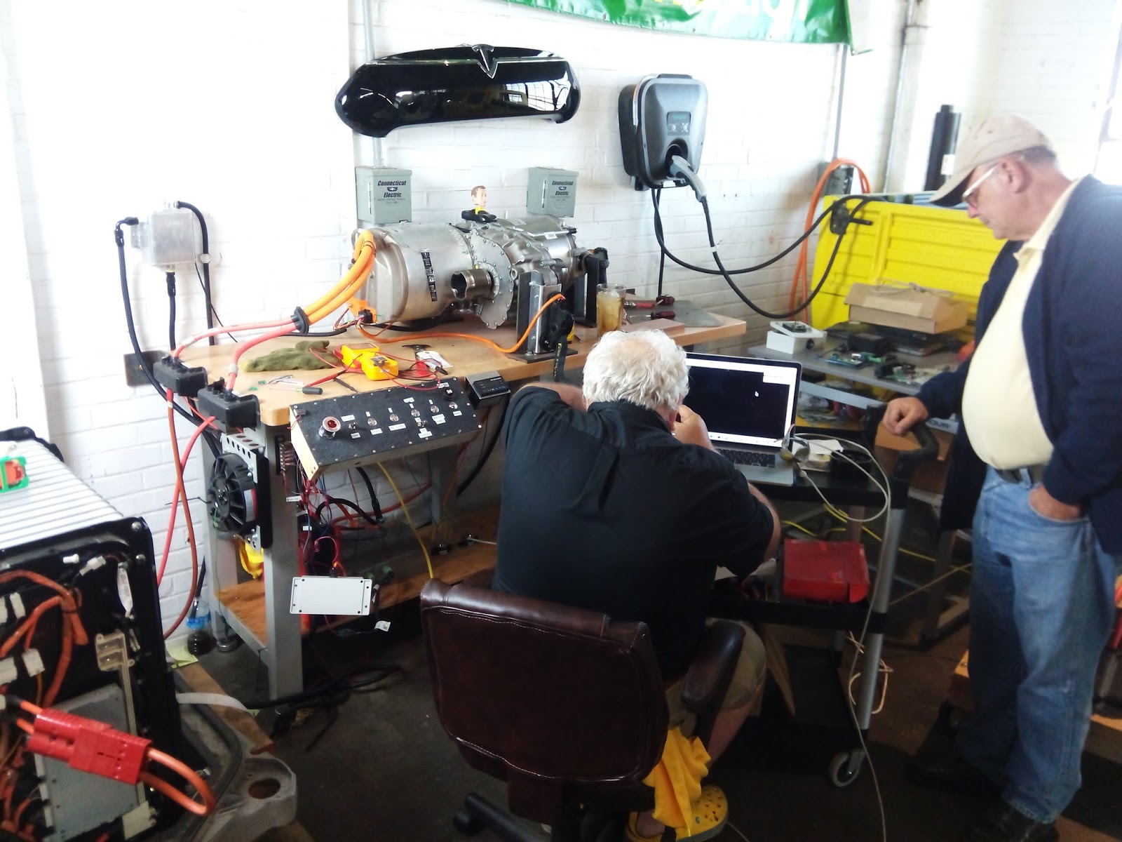
Session: Jack Rickard - Tesla Drivetrain Demonstration
We moved into the workshop area where Jack's Tesla drivetrain test bench is located. He showed us the control panel which operates contactors and simulated the brake pedal. He showed us the Arduino code that drives commands to the motor controller, and then he engaged drive and spun the unit up. He demonstrated forward, reverse and neutral and creep mode.
Here is a short video from his demonstration.
For longer video and a far more detailed description of the reverse engineering of the Tesla drivetrain, please see the relevant EVTV videos here.
Now we're packing up to go to the BBQ at Jack's house. It looks like this will be the first year we don't get rained out.
After I called the Zivan repair service and described what I was seeing, they told me to send it in for testing. After they ran it on the bench, I got a call from Mark, saying it was fine. Here's what he said, any errors or omissions are mine. I've been learning about the mysteries of battery packs on the streets and shady blogs, so I was happy to have another data point.
Mark said that the pack should be overcharged. Specifically my pack should be charged aggressively up to 157V with the T-125 battery setting "4" on the rotary switch. If I'm concerned about charging it too hard, I can set the switch to "3" which offers a slightly gentler charge for T-105 type batteries. After 12-18 months the batteries should be mature and I can switch back up to "4" and drive them a little harder. 110% - 115% overcharge is OK.
The lower-voltage cells have to be allowed to charge up to the level of the higher-voltage batteries. This is what Jack Rickard calls a "top balancing" scheme, which he says is wrong for lithium batteries, but he doesn't believe in lead-acid so it may be valid.
For the charging-state LED, a fairly-long yellow is OK, which represents the 80% to 100% stage. I thought it should be much shorter, adding to my distress over the observed voltage.
Now having explained all this, I still have exactly the same symptoms that another person at Zivan diagnosed the charger as faulty and I should send it in. This exercise cost me $70 plus shipping with nothing to show for it but a little more knowledge.
After I redid the whole charging system with the J1772 connector wired in, I did a short 3 hour charge and took it to the car show. I noticed that the performance was rather sluggish, but the voltage was right about 120V DC and the PakTrakr state of charge was 100%. Yesterday I decided to trust the charger and let it go through the full cycle without panicking and pulling the cord. Well imagine my surprise when it put 13.11 KWH into the pack over the course of 10:33. I had been doing about 8 KWH over 6 hours previously. The voltage peaked at 153.3V DC and dropped down to 132.2V DC shortly after disconnecting the charger.
13.11 KWH is far beyond what I calculated for the 80% to 100% charge capacity, so I'm hoping that the pack was just very thirsty because I hadn't been charging it all the way up. I did a short drive around the back yard today and the acceleration was neck-snapping like I remember from my first drive. I hope I haven't damaged the pack. If you know me, you know I'm a bit of a pessimist and I have this sinking feeling in the back of my mind that I now own a 10 mile pack. Well, I'll do some range testing and see how it looks. I just don't have the spare cash for a lithium pack so I'll have to make this work for as long as I can.
Earlier in the week I booked a time slot at John's North County Brake shop for a 4-wheel alignment. My cow-orker Deb has all of her work done by John and highly recommended him.
Today is Solar Appreciation Day at my company REC Solar. We get this day off every year to celebrate the end of winter and we're supposed to go out and enjoy the sun and the outdoors. I took the opportunity to drive the 914 into town and get the wheels aligned to make sure I'm tracking correctly down the road and not wasting energy on excess friction. I certainly enjoyed the sun on the drive in and out with the targa top off!
I pulled in and John wondered if the car was nuclear powered! He has a tricked-out golf cart that shares a lot of the same technology so he was familiar with the overall design of the car. John called his friend over from the Robb-A-Cart golf cart shop across the street to check out the car too. I discussed an overcharging situation I was having with my Zivan charger and Robb suggested that I contact Elcon in Sacramento as they do repairs on Zivans there without having to ship back to Italy. In fact several people came by the shop as the work was ongoing and were interested, so I explained the design several times.
First John adjusted the torsion bar bolts on the front suspension until the car was level side to side.
The rear wheels were pretty good, only 1/4" or so out of alignment. It wasn't clear how to make the toe adjustment, so I Googled it on my phone and found that two bolts needed to be loosened at the front end of the trailing arm. The arm is then adjusted with large tools, then the bolts are tightened back down. The passenger side went easily, but the driver's side wouldn't budge until he put a big pry back farther back into the space between the hub and the shock tower, and it came loose.
Then he went back to the front wheels and found, to no surprise, that the wheels were badly out of toe due to my replacement of the tie-rod ends. A quick adjustment brought them back into alignment.
The car now has all 4 wheels pointing in the right direction and the steering wheel is level!
On the way home, I stopped into the battery shop and showed Jim the car which was now full of his batteries. He was impressed, as were two folks on motorcycles that were at the shop at the time. I have a feeling I'm going to be explaining the car everywhere I go, but I'm looking forward to it!
The EA kit just has you bolting multiple ring connectors to the positive and negative terminals of the auxiliary 12V battery. As I was working on different systems on the car, I had to bolt and unbolt over and over. I realized that this was really inconvenient and also possibly dangerous if I needed to disconnect the battery in a hurry, like in a crash or fire. Since I had used an Anderson connector on the charger output, it made sense to do the same for the auxiliary battery. I crimped all of the incoming and outgoing wires into the connector pin to make everything nice and clean. Oh and I put wire loom on everything in sight!
Well it's over a year since I started the project and today I put the batteries into the car! I just want this to be over so I drive the car...
I loaded them one by one and they're very heavy! I bought a rubber loading strap from the battery place which hooked into the two plastic brackets molded into the top of each battery. I had to be careful not to bang them into the body or drop them, and everything turned out OK. Here are the saddlebag batteries.
And this is the former engine bay.
This is the former gas tank area.
This is the former front trunk / spare tire area.
Here's the full front area with the charger in place.
I then started hooking up the battery bus bars.
I put all of the battery bus bars in place as a mockup and found that there was one missing! Another final insult from EA! I had to buy some copper stock but the best I could find was too thin, so I had to double-up. I had to get some 1" shrinkwrap too.
Measuring and bending the double-thickness was difficult to get right. I had to put the shrinkwrap on before I started bending the second end.
And it's complete, short of a little fine tuning.
Here it is installed, looks almost factory-stock.
The last missing piece was a copper bus bar going between the two bottom terminals on the motor. I thought about making it out of a small piece of leftover 2/0 battery cable and two lugs, but since this is going to be exposed to the road, I decided to build it the way EA would have, if they had shipped it to me... And here it is.
Here it is bolted to the bottom of the motor, just like it should have looked.
Next I bolted up the bus bars in place to all of the battery posts. I then followed the directions in the EA manual and checked the voltage of each battery bank, and everything looked good. The last connection to make was the most-negative battery's negative terminal to the most-negative post. This is where it got exciting... I touched the lug to the terminal and it made a big spark! The manual didn't say anything about that and I was worried I had a short somewhere. I started unbolting the cables between the battery racks and checking voltages and grounds. I couldn't find the problem and it was getting dark so I figured it was smarter to sleep on it.
I decided to check in with the accumulated knowledge of the 914 electric conversion world on the 914EV newsgroup. Here's my post:
As I mentioned in the previous message, today I was going to make the
motor turn for the first time. I had all of the battery bus bars and
cables attached, except the final connection from Battery 14's Neg
terminal to the most-ground post. All of the partial-pack voltage
readings matched the manual's checklist. When I went to put the final
lug on the mount-ground post I got a big spark, which I assume is a
short somewhere.
I started trying to narrow down the problem by isolating the battery
boxes, removing cables from battery terminals, the controller, the
motor, the contactor. I couldn't get rid of the spark.
In frustration, I put my meter between the battery and the most-ground
post and found I had a current draw of 0.3A. Not really much, but
enough to make a spark and make me think twice about proceeding. This
is with the aux battery disconnected, the DC-DC disconnected, the
motor disconnected, key off and breaker off. None of the car's 12V
features are on.
The only thing out of the ordinary is a PakTrakr system, with a
voltage sensor wire on each of the 20 batteries. I disconnected each
PakTrakr unit's power supply wire and the LEDs all went dark. Even
when powered up, the PakTrakr should pull no more than 32 mA, and I'm
seeing about than 10x that.
I got several great suggestions back almost immediately. The gist of the problem is the spark was from the current draw on the big capacitors in the motor controller. The next morning I was convinced it was the source of the problem by holding a heavy-gauge jumper wire between the cable and the battery terminal. I held it there for 1 minute, took it off and touched it again and there was no spark! I bolted the terminal in place and everything was good!
Next up, wiring up the PakTrakrs and the first attempt at spinning the motor!
Just before I left for EVCCON, my battery order arrived. Well, I should say the second battery order. They previously shipped the correct US Batteries 125XC units, but with the wrong terminals. They kit requires, and I specifically asked for, "small L-posts" that the battery bus bars and cabling attach to with a bolt/washer/washer/nut assembly. The first order came with standard automotive round terminals. It was clearly their fault, but there was every chance that they could have charged me a return fee or shipping fee. Luckily, they were able to pick them up and take the back to the factory in the same truck that dropped off the new order.
Here is the full load of 20 batteries. It was a definite test of the shocks and springs in my truck.
You can see the correct L-post below, along with the factory-supplied "SpeedCap" that opens all 3 watering opening with the twist of the wrist. Pretty cool, otherwise I'm unscrewing, checking and screwing 60 openings all the time.
I placed an order for the batteries with my local Battery Systems store. They matched the best price I could find so I felt good about supporting a local business. Unfortunately after the two week wait, the batteries arrived with the wrong terminal. My son took the truck to pick them up, so I didn't realize the problem until he brought them home.
The EA kit explicitly needs the "Small L" terminals, because the battery bus bars are cut, bent and drilled to exactly fit. I don't know where the terminal spec went wrong, but Battery Systems is sending these back and ordering a new set. They'll be here in 3 weeks as they have to be ordered directly from the factory.