Wednesday, August 3, 2011

Installing the Charger

So my next series of disappointments came with the charger.  The directions call for a "booster" and a charger that I don't own in my kit.  This is the mounting plate in place as a template for drilling the hinges.  The booster and charger are supposed to mount vertically on this plate.


My kit came with a large, single unit Zivan charger that won't bolt vertically to the area shown in the directions.  With some Google image searching, I found other EA kit people with the same unit and recognized the L-shaped mounting bracket that is left in my getting-very-small parts pile.  I bolted it into place.


Here is the charger bolted on the bracket.  I had to drill drill four mounting holes in the bottom of the plate.


And here it is in place in the car.


This is the Anderson connector that ties the charger's high-current DC output to the battery string.  I drilled a hole in the side of the bracket and put the two conductors through a grommet.  This will allow for better wire management as the charger bracket pivots up.  Unfortunately EA instructions to make the red conductor back to the Battery + post still ended up about 8" too short, so I had to re-make that to the proper length.


Here is the whole thing installed, pivoted up and propped into place by the supplied "propping stick".


All I have left here is to run the AC input cable around the edge and into the wiring box.

Front Battery Box Continues

The front battery box turned into a comedy of errors orchestrated by ElectroAuto.  Just imagine the new swear words I invented just for the special occasions the directions were wrong.

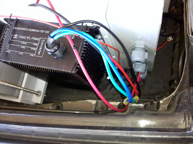
First, I was sold a different DC/DC converter than is documented in the directions.  The documented one has mounting posts, allowing multiple wires to be landed on the two inputs and two outputs with small closed-end connectors.  Mine came with a small wiring harness of 4 wires, which makes it tough to do a 3-way splice as needed in a couple of places.  What I did was use the multiple tab feature of the fuse block and terminal block in the wiring box to make the necessary connections.

I completed wiring up the DC/DC converter on the bench.  Now we're ready to get it into place.


I'm really good at following directions, but as you can see there isn't enough room to fit the box in at the front.  Now this is the wiring box that I added and it's tighter than I want, so I can't blame them for this, but as we move around the front and put the auxiliary battery in place, the plastic of the main box is bent in significantly, and the 6V batteries would never fit.


Another problem I noticed was the path of the battery box exhaust tube to the vent.  It looks OK from this angle, but the height difference is about 4".  This is going to be tight.


I cut away some of the small tray that was shaped like the front of the spare tire to hold it in place, giving sufficient clearance around the wiring box.


I carefully measured the gap between the back of the box and the firewall and found I could go another 1.25" back, giving sufficient front clearance.


This is after drilling new holes, rustproofing with POR-15, bolting the rack back into place and test fitting the battery box.  It's still tight, but everything fits.


I then completed roughing in the wiring from the harness into the wiring box.  Once I wire up the charger's 120V AC, then I'll test everything, tidy up the wires and wrap with split loom.


And now on to the charger.

Front Bumper Restoration

The next phase of the conversion is the front battery box area which meant that I needed to complete the restoration of the front bumper components.  This turned out to be nicely straightforward until I forgot something...

The main problem with the front bumper, besides just being dirty and gritty, was the rubber cap - it was cracking a bit on the left end and had silver paint overspray on most of it.


I first cleaned the rubber well with my eco green cleaning fluid, then wet sanded it from 180 grit all the way through 2000 grit.  It came out smooth and black and not a hint of silver paint.  Next I mixed up some epoxy and filled the small cracks on the passenger end and when dry sanded that down the same way.  In hindsight I should have mixed some black tint into the epoxy because it looks a bit like grey graining in black stone.  This is before sanding down.


Next I cleaned the horn and fog lights and mounting hardware.  I bolted the horn bracket with a rubber spacer and wired everything up with new connectors crimped on the ends.  The wiring up to the fog light is truly bizarre with a spade connector for ground, and a soldered wire stub that fits into a brass barrel and held in place with a setscrew...


It's important to leave the bolts a little bit loose because the positioning of the horns and lights will be finalized when the bumper is mounted and the silver grills are test-fitted.


And here we are!  The silver grills were in pretty good shape, so I resisted the urge to sand down and repaint.  They're easy to pop off so maybe later...


What I quickly realized is that I'm missing the trim piece that bolts to the bottom of the bumper!  When I bought the car it was in very bad shape - bent, dented, chipped paint, the works.  I did some work on it a long time ago, grinding off the paint and starting to shape the metal back into place.  At some point I need to go back and finish the shaping and paint it, remove the bumper, bolt the trim on and then bolt the whole thing back on.

Well it's starting to look like a car again!

Sunday, July 10, 2011

Front Battery Box Assembly

The last thing I tackled this week is the construction of all of the components of the front battery box.  The box holds batteries, but is also the platform for the auxiliary battery, the DC/DC converter and the relay board.  As with the contactor parts, I put the relays and the connector strips into another weatherproof enclosure.

Here's where things went horribly wrong.  The aux battery and DC/DC board mounts to the battery box via threaded studs and 1/2" long 1/4" bolts.  Unfortunately the holes were all the wrong size and the studs were not installed at the factory, as the instructions assume.  It took me a while to figure out the right stud to use, drill out the holes, install the studs, then moved forward.


Since I'm bolting a weatherproof enclosure into this area, I had to drill holes slightly below stock.  I also had to clean up the plastic welding bead on the inside joint.  I melted it with my soldering gun, then scraped away the excess while it was still warm.


Another big problem with the directions is it assumes a certain DC/DC model with bolt terminals on the top, not with a cable coming out the top like mine.  Reading ahead I see I'll have to double-lug some of the spade lugs to work around this problem, but I'm getting very flexible and creative now.


And finally here is the relay board in its enclosure, ready to have wires run into it.  I'll dummy everything up and figure out how best to run the wires into the box using probably three gland nuts.


This is the aux battery mounting area.  I'll have to pick up a battery tomorrow to be able to continue cutting and mounting the rest of the cables.  For the record, it's a U-1 style 12V battery, maximum size 7 3/4" L x 5 3/16" W x 7 5/16" H, with 1/4" bolt-on terminals.


Well that was the end of a long, hot week.  I think I need a break from the project for a while!

Continuing the Wiring Harness

With the DC cabling pulled, a bunch of low voltage and signal wires go in.  This is all in the vicinity of the pack positive stud.  Another thing I object to in the kit is the use of these in-line spade terminals.  I'll have to figure out how to make them waterproof or replace them with something that is.


Here's another angle showing all of the wires coming up and into the mid-compartment.  These loose wires will all end up in some split-loom.


And here we go into the front battery area.


Back in the engine compartment, there's a pair of wires coming from the backup light signal from the transmission to a splice block to join the wires for the and the motor overtemp wires.  This is another one of these splice things.  I tried to use enough tape to make it waterproof and then ziptied it to the motor mount.  I'll keep an eye on it and replace if necessary.


Circuit Breaker Preparation

The circuit breaker is supposed to bolt to the side of the left speaker enclosure.  I don't like this idea much because the speaker enclosure plastic is pretty brittle, and it makes me sad to cut a big chunk of plastic out of it.  Replacements are more than $100 so it's a big commitment.  Of course the cables are designed and cut with this placement in mind, so there's no getting around it.

First I placed the mounting bracket and marked where the holes need to be drilled.


Then I followed the directions to cut away the area where the cable will bend over and get bolted on.


I wanted to stay with the black motif so I painted the aluminum bracket, mounted it to the speaker enclosure and then the circuit breaker to the bracket.


Here's where the breaker will go.  I want to get the carpet installed before I permanently mount it, so this will happen much later.

DC Power Harness

The next major step is to build the high-voltage DC harness that brings power from the front batteries, through the circuit breaker and then to the contactor and on to the controller.

ElectroAuto has you measure two 2/0 welding cable, plus a 10 ga ground wire and a 4-conductor signal cable, then tape everything together at the proper offsets.


The instructions provided a convoluted set of steps using "mechanic's wire" to prep for pulling the cabling through the heater duct, and you need an assistant to do the cable pull.  I decided to use my fishtape, and it was easy to do by myself.  Here you see the fishtape running into the heater duct from the rear of the car to the front.


The tip of the fishtape sticks up out of the hole just below the fuse block.


I put the end of the fishtape through the lug hold, then strapped it into place with a ziptie.


I then wrapped it in tape to make for a smooth pull.


At the end of the pull, you want a tape marker to just be coming out of the heater tube in the engine compartment.


And this is the other end, with the cable waiting to be bolted to the circuit breaker.  I'll have to do some minor pull adjustments to get enough cable.


After finishing the prep, I put the "CA Plug" in place, and used the same silicon as for the saddlebag battery rack.  The CA Plug is slightly angled so it didn't want to stay in place.  I helped it by sticking a screwdriver in as a wedge.


One small complication due to my use of the weatherproof enclosure.  The end of this cable bolts to the contactor but the lug is about 1/16" too wide to get through the weatherproof gland nut.  My solution was to grind just enough off to get it to fit through.  Unfortunately I forgot to do the grinding before I pulled the cable, so the grinding occurred on the ground under the back of the car.


Final connections on each end happen in later steps.

Finishing the Potbox

Previously I had mounted the potbox unit inside the weatherproof enclosure and mounted it.  To complete the job, I had to run the potbox signal cable to the controller and the potbox microswitch.  Here you see everything in place, running through a weatherproof cable gland nut to split-loom, and the clear cover on and screwed down tight.  Then you can see the wiring landed on the controller.


Fuse Block Conversion

Another of the evidence of 37 year-old technology in the car is the fuse block.  It uses Good-And-Plenty sized glass fuses that are held in place by heavily oxidized and dirty copper spring contacts.  Electrical system glitches waiting to happen.  I bought a modern, swap-in replacement from J West Engineering, and here are the steps to swap it out.

Here's the original, disconnected from the underside of the dashboard.  You can see the spring clips.


And here is the top.  You can see the round relays, along with a bit of dirt..


Here's the J West replacement.  It's shaped as a bolt-in replacement, but uses modern fuses.  It also comes with nice fuse labels, for each 914 model year.


Here I'm swapping wires from the old fuse block to the new one, one wire at a time to avoid problems.  I removed a bunch of the cloth tape to give more wire access.  This cloth tape has given its life.  I plan to remove it all throughout the car and replace it with split-loom cable protector.


Here's the completed swapover.


I then moved the relay bases over to the new unit.


I bought all new relays right at the start of the project, so in they go.


And here it is mounted back into its proper place.  I've placed an order for a second fuse block and will mount it under the dashboard too, to provide fuses for new electrical devices in the car such as the stereo (switched and unswitched), Droid charger, GoPro video camera charger, windshield washer pump motor and eventually heating and cooling systems.


The one downside of the unit is it doesn't have bars across multiple input terminals like the factory one, you have to make up little jumpers which is OK, but not optimal.

Edit: I have been notified that there are indeed bridged terminals built into the unit, I will investigate later.