Sunday, July 10, 2011

Front Battery Box Assembly

The last thing I tackled this week is the construction of all of the components of the front battery box.  The box holds batteries, but is also the platform for the auxiliary battery, the DC/DC converter and the relay board.  As with the contactor parts, I put the relays and the connector strips into another weatherproof enclosure.

Here's where things went horribly wrong.  The aux battery and DC/DC board mounts to the battery box via threaded studs and 1/2" long 1/4" bolts.  Unfortunately the holes were all the wrong size and the studs were not installed at the factory, as the instructions assume.  It took me a while to figure out the right stud to use, drill out the holes, install the studs, then moved forward.


Since I'm bolting a weatherproof enclosure into this area, I had to drill holes slightly below stock.  I also had to clean up the plastic welding bead on the inside joint.  I melted it with my soldering gun, then scraped away the excess while it was still warm.


Another big problem with the directions is it assumes a certain DC/DC model with bolt terminals on the top, not with a cable coming out the top like mine.  Reading ahead I see I'll have to double-lug some of the spade lugs to work around this problem, but I'm getting very flexible and creative now.


And finally here is the relay board in its enclosure, ready to have wires run into it.  I'll dummy everything up and figure out how best to run the wires into the box using probably three gland nuts.


This is the aux battery mounting area.  I'll have to pick up a battery tomorrow to be able to continue cutting and mounting the rest of the cables.  For the record, it's a U-1 style 12V battery, maximum size 7 3/4" L x 5 3/16" W x 7 5/16" H, with 1/4" bolt-on terminals.


Well that was the end of a long, hot week.  I think I need a break from the project for a while!

Continuing the Wiring Harness

With the DC cabling pulled, a bunch of low voltage and signal wires go in.  This is all in the vicinity of the pack positive stud.  Another thing I object to in the kit is the use of these in-line spade terminals.  I'll have to figure out how to make them waterproof or replace them with something that is.


Here's another angle showing all of the wires coming up and into the mid-compartment.  These loose wires will all end up in some split-loom.


And here we go into the front battery area.


Back in the engine compartment, there's a pair of wires coming from the backup light signal from the transmission to a splice block to join the wires for the and the motor overtemp wires.  This is another one of these splice things.  I tried to use enough tape to make it waterproof and then ziptied it to the motor mount.  I'll keep an eye on it and replace if necessary.


Circuit Breaker Preparation

The circuit breaker is supposed to bolt to the side of the left speaker enclosure.  I don't like this idea much because the speaker enclosure plastic is pretty brittle, and it makes me sad to cut a big chunk of plastic out of it.  Replacements are more than $100 so it's a big commitment.  Of course the cables are designed and cut with this placement in mind, so there's no getting around it.

First I placed the mounting bracket and marked where the holes need to be drilled.


Then I followed the directions to cut away the area where the cable will bend over and get bolted on.


I wanted to stay with the black motif so I painted the aluminum bracket, mounted it to the speaker enclosure and then the circuit breaker to the bracket.


Here's where the breaker will go.  I want to get the carpet installed before I permanently mount it, so this will happen much later.

DC Power Harness

The next major step is to build the high-voltage DC harness that brings power from the front batteries, through the circuit breaker and then to the contactor and on to the controller.

ElectroAuto has you measure two 2/0 welding cable, plus a 10 ga ground wire and a 4-conductor signal cable, then tape everything together at the proper offsets.


The instructions provided a convoluted set of steps using "mechanic's wire" to prep for pulling the cabling through the heater duct, and you need an assistant to do the cable pull.  I decided to use my fishtape, and it was easy to do by myself.  Here you see the fishtape running into the heater duct from the rear of the car to the front.


The tip of the fishtape sticks up out of the hole just below the fuse block.


I put the end of the fishtape through the lug hold, then strapped it into place with a ziptie.


I then wrapped it in tape to make for a smooth pull.


At the end of the pull, you want a tape marker to just be coming out of the heater tube in the engine compartment.


And this is the other end, with the cable waiting to be bolted to the circuit breaker.  I'll have to do some minor pull adjustments to get enough cable.


After finishing the prep, I put the "CA Plug" in place, and used the same silicon as for the saddlebag battery rack.  The CA Plug is slightly angled so it didn't want to stay in place.  I helped it by sticking a screwdriver in as a wedge.


One small complication due to my use of the weatherproof enclosure.  The end of this cable bolts to the contactor but the lug is about 1/16" too wide to get through the weatherproof gland nut.  My solution was to grind just enough off to get it to fit through.  Unfortunately I forgot to do the grinding before I pulled the cable, so the grinding occurred on the ground under the back of the car.


Final connections on each end happen in later steps.

Finishing the Potbox

Previously I had mounted the potbox unit inside the weatherproof enclosure and mounted it.  To complete the job, I had to run the potbox signal cable to the controller and the potbox microswitch.  Here you see everything in place, running through a weatherproof cable gland nut to split-loom, and the clear cover on and screwed down tight.  Then you can see the wiring landed on the controller.


Fuse Block Conversion

Another of the evidence of 37 year-old technology in the car is the fuse block.  It uses Good-And-Plenty sized glass fuses that are held in place by heavily oxidized and dirty copper spring contacts.  Electrical system glitches waiting to happen.  I bought a modern, swap-in replacement from J West Engineering, and here are the steps to swap it out.

Here's the original, disconnected from the underside of the dashboard.  You can see the spring clips.


And here is the top.  You can see the round relays, along with a bit of dirt..


Here's the J West replacement.  It's shaped as a bolt-in replacement, but uses modern fuses.  It also comes with nice fuse labels, for each 914 model year.


Here I'm swapping wires from the old fuse block to the new one, one wire at a time to avoid problems.  I removed a bunch of the cloth tape to give more wire access.  This cloth tape has given its life.  I plan to remove it all throughout the car and replace it with split-loom cable protector.


Here's the completed swapover.


I then moved the relay bases over to the new unit.


I bought all new relays right at the start of the project, so in they go.


And here it is mounted back into its proper place.  I've placed an order for a second fuse block and will mount it under the dashboard too, to provide fuses for new electrical devices in the car such as the stereo (switched and unswitched), Droid charger, GoPro video camera charger, windshield washer pump motor and eventually heating and cooling systems.


The one downside of the unit is it doesn't have bars across multiple input terminals like the factory one, you have to make up little jumpers which is OK, but not optimal.

Edit: I have been notified that there are indeed bridged terminals built into the unit, I will investigate later.

Rear Battery Rack

I blasted through a lot of work this week, so I'm going to make a small post for each area.  This one is on the finishing the rear (engine compartment) battery rack.

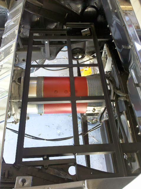
Alert readers will remember my pain of trying to fit the rack into the space.  I had to cut out the engine cover latch and a couple of trays.  The hell-hole didn't start out too bad, but it wasn't completely dealt with by the body shop and rust kept percolating through the paint.  I tried rust-converter and it helped but not completely.  I then went to the POR-15 and painted the whole engine compartment.  It both halted the rust and added to the black motif.  It also covered the scratched paint from all of the times I tried to put the rack in and pull it out again.

Here's the rack support sticking up, waiting for the rack.


You can see the rack is bumping against the semi-vertical brace on the side of the engine compartment.  I've seen others grind the rack away just enough, but I just finished pounding out the firewall, so several carefully placed hits and a grinder to smooth it, the rack had enough clearance.


On the passenger side, there is a triangular plate, which I cut away, leaving enough clearance.


And viola!  The rack is home for the first time in a test fit.  I was surprised by how tight it fit - there's only a few millimeters from the back of the rack to the front of the transmission adapter, and again only a few millimeters between the top of the motor and the bottom of the rack.


Here's where the triangular plate was, after I removed it and ground everything smooth.


And this is the driver's side where I pounded it, then ground everything smooth.


These shots are after the POR-15 treatment.


And now the rack is back in place and ready to bolt to the vertical supports and the metal sheet behind the seats.


And here is how tight the clearance is between the rack and the motor adapter plate.  Just a tiny bit of daylight.


Of course I tried to fit in the battery boxes, but they need a little bit of trimming on the plastic edges.  I'll save that until later.

Thursday, July 7, 2011

Signed up for the EVTV Electric Vehicle Conversion Convention

I've been watching hundreds of hours of video of the EVTV electric conversion guys, and just tonight signed up to go to the first electric car builder convention just outside St. Louis in September.  Check out the itinerary, speakers and expected cars.

It turns out an old colleague of mine at IBM Austin, Fred Behning, is working on an electric conversion of his Bugeye Sprite and will be at the convention too.

Tuesday, July 5, 2011

A flurry of Work - Wipers, Ventilation and Washers

Well it's the 4th of July weekend here and that means I get Monday off for the holiday.  I decided to take Tuesday through Friday off, giving myself a 9 day vacation.  I intended to really bang through a lot of work on the car and so far it's working out well.  The only downside is it's the hottest week of the year, starting at 112F on Friday, slowly dropping to a peak of 96F today.  The car is under a carport on the east side of my workshop building, so it's out of the direct sun, but it still gets very, very hot.  I'm starting early in the morning and staying hydrated, no problems so far.

With the former-fuel tank area successfully reshaped for the battery box, I had to restore and reinstall everything that goes in under the cowl.  Starting in deep and working my way out, I installed the windshield wiper mechanism.  After cleaning, it went in pretty smoothly.  Of course I forgot to take a picture of the control connector during the teardown, but a quick Google search found this great picture on the Pelican Parts forum.


With that in place, I cleaned and reinstalled the central airbox and driver and passenger flapper units, installed the hoses and attached the control cables.  Warning: this is a non-trivial process.  I used a combination of two tutorials on 914 World, an expansion and clarification of the tutorial by Chuckles McGroover (probably not his real name...) on his highly-detailed conversion blog, and the Haynes manual.  My sincere thanks to everyone for their pioneering work in this tricky area.

First I installed the defroster vents.  The original foam gaskets had turned to powder, so I used weatherproofing strips around the edge.  The tricky part came to sticking them through the holes in the metal at the top of the dashboard - the foam would catch and not go through smoothly.  I ended up gently scotch-taping some paper around the foam strips, slid them through the holes and gently pulled the paper out.


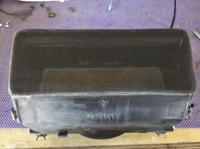
I then prepped the air blower box.  When I did the teardown, I found years worth of dirt, leaves and unidentifiable crap inside.  I decided to follow web advice and put a piece of screening material over the top of the box.  My first attempt to hold it in place was with a couple of long zip-ties, but the area is *very* tight and they wouldn't fit and ended up popping off anyway.


The working solution was to epoxy the screening around the edge of the box.  A fairly permanent solution, but I don't intend to be replacing it anytime soon.


Installation was a *major* pain, as it is so tight, right-to-left between the two mounting brackets.  I ended up loosening the upright brackets holding the top of the cowl to the shelf of the firewall.  It was just enough to force it into place and get the two screws started.


I then followed the tutorials to attach the control cables, and mounted the flapper units, then ran some new flexible hose where it needed to go.  So here is the complete job, starting with a wide view, then panning from driver's side to passenger.  I like the black motif.


Finally I worked on replacing the spare-tire-pressure windshield washer system with a small electric pump.  I ran the wires long and fed them through the hole where the washer hose went up into the steering column's valve, and will replace it with the 944 electric control I bought a long time ago.  I bought a new set of squirter nozzles since the rubber on the originals was in rough shape where it fits into the hole in the cowl.


Coming up in the next entry - the engine bay battery box goes in!