Sunday, September 18, 2011

Charger Plug and Wiring

The EA kit comes with a nice weatherproof 120V socket with male pins, designed to take the female end of an extension cord.  The manual has a suggested through-the-bodywork installation process.  After all of the work I did with this car, there's no way I'm drilling a big hole through it.  I decided to mount a box inside the front trunk, giving easy access by popping the front trunk, plugging in, the laying the trunk lid down.  This also gives me the option of moving it in the future, or adding a J1772 plug when I add a 240V charger.

I got a 4"x4"x4" plastic box with a removable gasketed lid at Lowe's.  I found a place for it in the front left corner of the front trunk, next to the battery box.  I mounted it in place with two bolts and a rubber strip to cushion the box from the vibration.


I then drilled a hole in the lid, sized to the plug from the EA kit.


Here's the plug in place for a test fit.


I mounted the plug with some nice stainless steel pan-head allen key bolts and nylock nuts.  I ran the EA-supplied cable from the plug and out of the box through a cable gland.


Here it is in place.


Last step was to land the wires onto the terminal block.  The top three terminals run over to the charger.

Motor Overtemperature Indicator

The next disappointment from the EA kit is the handling of the motor temperature overheat indicator.  According to the manual, the wires from the motor temperature switch are wired to the red alternator light in the left-side gauge cluster.  Unfortunately, when I powered up the12V circuit, the light went on, indicating an overtemp situation.  This is clearly not the case, so I did some investigation.

The Warp 9 includes a temperature snap switch that *breaks* the circuit when too hot.  This action goes against the way the EA wiring diagram is designed.  I can only think that the Warp motor changed spec somewhere along the line and the EA manual wasn't updated, or the EA manual has been wrong all along.  Either way, I had to make this work.

The normal way to do this is with another small relay.  I wrote up the circuit below.


The key is to energize the relay through the overtemp switch circuit, but wire the "unenergized" terminal to the indicator light.  It will only light when the overtemp switch fires and breaks the circuit.

Luckily I found a cheap Tyco relay online, and mount and wired it into a small space in the front relay box.


With the circuit now wired up, I turned the switch and the light stayed off.


I then disconnected the motor overtemp switch wire, and the light went on!  Success!  I'm getting to be a real champ at diagnosing and fixing EA problems.

Energizing the 12V circuits

After the ignition switch was wired in, there was nothing stopping me from hooking up the battery and turning the key.  This should help me test the 12V circuits.

I had my son standing next to the battery with a fire extinguisher as I turned the key.  BEEEEEEEEEEEEEEEEEEEEEEEEEEEEEEP!  I nearly jumped out of my pants.  I had tucked the horn wire into a space in the steering column, completing the circuit.  As soon as I turned the key, the horns went off at full volume.  I switched off the key and pulled the horn wire out.  I turned the key again and heard a click in the relay box.  I followed the diagnostic tests in the EA manual and immediately found a problem.  The green oil pressure indicator light is supposed to light up when the key is turned, indicating that the 12V circuit is on.  But the light didn't go on.  After tracing the wiring and checking with a meter, I found that the light bulb was bad!  I bought a box of replacement lights for the instruments, but that particular one still had its old bulb.  Lesson learned...  The rest of the EA tests with the batter and DC/DC converter were successful.

Next I tried pushing the electron pedal and heard the contactor engage with a loud clunk.  Success!

I don't have any of the original 12V devices in place like lights, blinkers, etc. so there was nothing else to test.  As I rebuild those parts of the car, I'll test them.

Ordering the Batteries - Wrong Terminals!

I placed an order for the batteries with my local Battery Systems store.  They matched the best price I could find so I felt good about supporting a local business.  Unfortunately after the two week wait, the batteries arrived with the wrong terminal.  My son took the truck to pick them up, so I didn't realize the problem until he brought them home.

The EA kit explicitly needs the "Small L" terminals, because the battery bus bars are cut, bent and drilled to exactly fit.  I don't know where the terminal spec went wrong, but Battery Systems is sending these back and ordering a new set.  They'll be here in 3 weeks as they have to be ordered directly from the factory.


Horn and Steering Wheel Installation

After I got the steering column in place, I decided to try installing the steering wheel.  I should have known there would be problems, as there was no horn button in the car when I bought it, along with a Momo aftermarket steering wheel.  The horn button (several actually) and a round metal ring were included in a box of parts I got with the car, so I tried to figure out how to get it all back together properly.


It turns out the metal ring is a standard part that provides a ground connection, completing the horn circuit and beeping the horns.  The problem is, no matter how I tried to mount the ring between the steering column and the wheel, it wouldn't fit.  There is a raised ridge around the ring, but the hole in the wheel is 55mm and the ring is larger than that.  To me this says the ridge has go point into the steering column, but it doesn't fit into that very well either.


The ring does the job of a compression friction fit of the horn button.


I'll have to go back again and see if I can make things fit.  I'm guessing the steering column is not quite compatible with this ring, but despite a lot of Google searches, I can't find an alternative ring or any advice on making this work.  I'm going to leave the wheel off for now as I finish up work on the dashboard area.

Steering Column Rebuild

Now that I have the ignition cylinder restored and new keys cut, I could move ahead and rebuild the steering column.  I sanded, primed and painted the metal housings, then built everything back in reverse order.


A major change I made was to swap in a 924 indicator / wiper stalk assembly, as it has an electric switch to control a windshield washer pump.  There is an article at Pelican Parts that guided me through the swap.  This is the 924 assembly I bought on eBay, after I moved the 914's white wire guides over.  You can see the red and brown wires at the bottom are extra, and don't have a guide slot. 


Next I added butt splices onto the two wires, to extend them down into the dashboard so I can wire them up to a fuse and the washer fluid pump.


Here I'm threading the extended wires through the gap in the bracket.  I gently slid the 914 wire guide into the bracket and slid the assembly over the steering shaft and onto the bearing.


I then ran the four long screws into the steering column bracket, securing the whole assembly.  And here we are, ready for the steering wheel.  This is an easy and very worthwhile retrofit, thanks to the evolution of the part from Porsche.

Keys and Locks

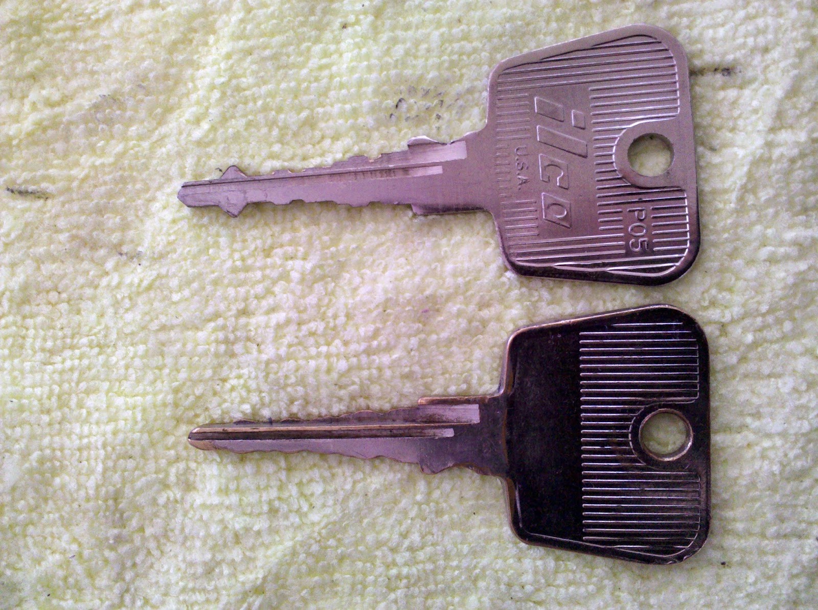
The original key was badly worn, to the point where it was difficult to start the car without significant wiggling.  As I was getting ready to rebuild the dashboard, I took apart the locks and thouroughly cleaned all of the components.  The dirt and grime of 37 years just kept pouring out.  I then took the keys, the ignition cylinder, the door locks and trunk lock to an automotive lock specialist in Morro Bay.

He made new keys from the ignition cylinder, and then further cleaned and tuned the locks.  They work very well now.  You can see the difference between the original key and the new one.


Transmission Punch List

Back when I did the transmission installation, I had a couple of remainder items.  The first was a plastic cover for the shifter linkage.  The second was a nylock nut to hold on the other transmission mount.

Let's do the nut first.  The nut was tricky because it's a metric M12 x 1.5.  12mm nuts are fairly common around here, but the 1.5 thread is not.  Most hardware stores in my area like Lowe's, OSH and TrueValue seem to stock the coarser 1.75, both in regular and nylock.  I had given up and was going to order a stupid nut on the web until I happened to be in the NAPA auto parts store in my town and viola!  They had it!  So now my transmission is firmly mounted on both sides with the correct nut, and it won't work its way loose.


Now onto the transmission shift linkage cover.  I didn't remove one from the car during the teardown, so I was searching around for a used one or a replacement.  I finally stumbled on one at Auto Atlanta.  I ordered it for about $25, only to be notified it was on backorder.  I waited for about 2 months for it to show up, and sadly it's not very good.  First, it's just a tiny bit too small, so it's extremely difficult to get around the linkage housing.  Second, it's made from very thin, brittle plastic so of course in my efforts to get it to fit, the lip cracked off.  I called up Auto Atlanta and the guy seemed to know exactly what I was talking about when I described the problem and my feelings that it's just not a very good product.  He explained that they can only get this part from a single supplier and they know they have problems with his size and material choice.  He readily gave me an RMA to ship it back to them.


Shortly after all of this I was looking for another part and I found a freaking transmission shift linkage cover in a cardboard box of parts from the previous owner!  Argh!  I installed it, using a hose clamp around the lip and it's great.  It looks like it was painted at some time in the past, so I'll remove the paint and get back to the original plastic and treat it with some back-to-black plastic lotion.

My Last Shipment from Electro Auto?

Today is July 2, 2011 and I think I just got my last shipment from Electro Automotive.  Well I am actually waiting for one final thing but I don't know that I'll ever get it.


The final part I was waiting for was the engine cover pins.  I placed my order on June 3, 2010, which is almost exactly 13 months ago.  Today I got a totally-stock, over the counter part from Summit Racing.  And EA sent it Priority Mail!  Why did it take them 13 months to get a stock part from a standard supplier, then decide to spent extra money to save a day in the mail?  Their business processes just boggle the mind.

Brake Work

It's been a while since the last update, but I've been making steady progress.  I found these great single-person brake bleed nipples at PelicanParts.  Since I'm working on my own, everything that helps me do things myself gets a shot.  These have a one-way valve that allows you to bleed the brake by backing them off 1/4 of a turn, pumping the brake until the air is gone, then tightening again.


 I replaced them on all four caliper units.


I'll fill and bleed the system later.

Next I moved on to the brake pressure sensor switch.  Alert readers will remember that only one of the wires was connected to the sensor switch, the other one was dangling.  I bought a new switch from Pelican Parts and replaced it.  The new switch has two connectors, but upon removing the old one, I found it was in good shape, yet had only one connector terminal.  I can only think it was a badly-done replacement, so I put in the new switch and put new connectors on the ends of the wires, running them through a rubber shroud.  It turns out the length of the connectors prevents the shroud fitting correctly, so I'll put right-angle connectors on soon.